Copy of Inductance Sweeps
Inductance sweep conducts a sweep analysis based on harmonic simulations to calculate inductance, reactance, Q-factor, losses, and other related parameters across different currents, voltage levels, or frequencies.
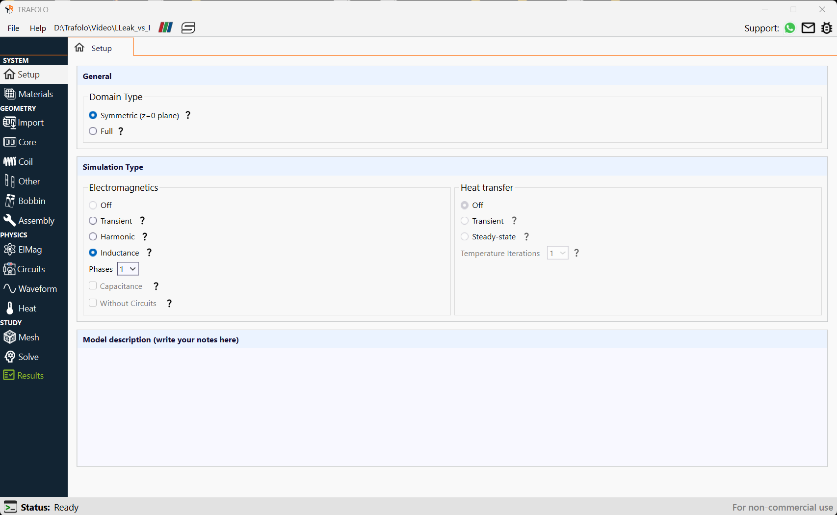
Setting Simulation Type
- In the Setup tab choose Simulation Type as Inductance.
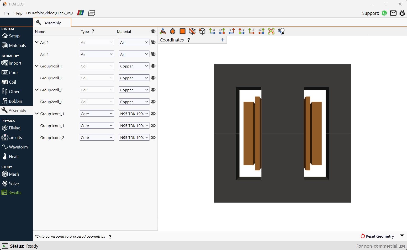
A Ferrite EE core is considered which consists of primary and secondary windings made of Copper. Litz wire is chosen for primary and secondary winding.
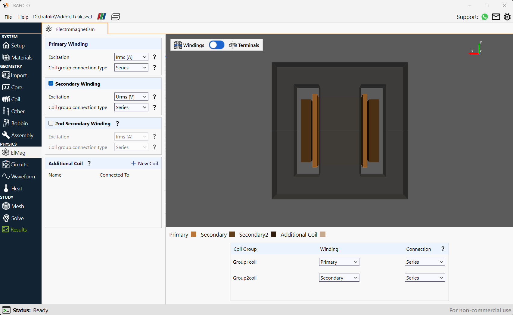
Configuring ElMag
- In Primary Winding set Excitation as Irms[A] and Coil group connection type to Series.
- Enable Secondary Winding.
- Set Excitation to Urms[V] and Coil group connection type to Series.
- Ensure Group1coil is set as Primary winding and Group2coil as Secondary winding.
Setting Parameters for the sweep
In this example, an inductance sweep is carried out for different current excitations (primary winding is excited using current in the ElMag section) at a fixed frequency. Inductance sweep can also be carried at different frequencies at fixed current excitation.
- Specify a Fixed Frequency of 100 kHz to solve the problem.
- Varying currents (0.5 to 10 amperes) were applied in the Primary Irms[A] list of Inductance Sweep.
- Set the value of Secondary Urms[V] to 0 for the Inductance Sweep in the Waveform tab.
This is equivalent to shorting the secondary winding or setting no resistance on terminals. This is done so that the resulting circuit inductance becomes the leakage inductance of the transformer.
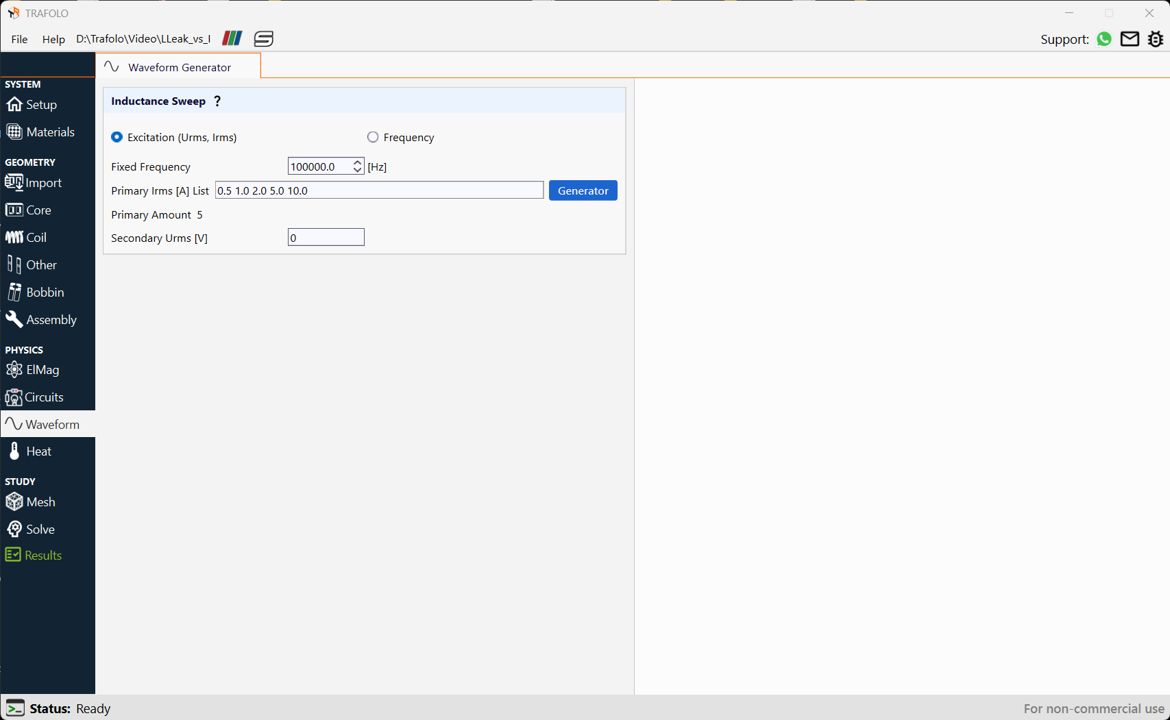
By setting Urms[V] as primary excitation and Irms[A] as secondary excitation, and then carrying out an inductance sweep for 0 Secondary Irms[A] calculates magnetizing inductance of the transformer. This is because the setting is equivalent to an open-circuit secondary winding.
Analyzing Sweep Results
Inductance and Magnetic flux distribution are analyzed in the Result tab.
Calculating Inductance
Inductance is calculated using two methods: circuits and energy.
The circuits method involves dividing complex voltage by complex current to extract impedance. The energy method involves integrating magnetic fields and dividing by the square of the primary current.
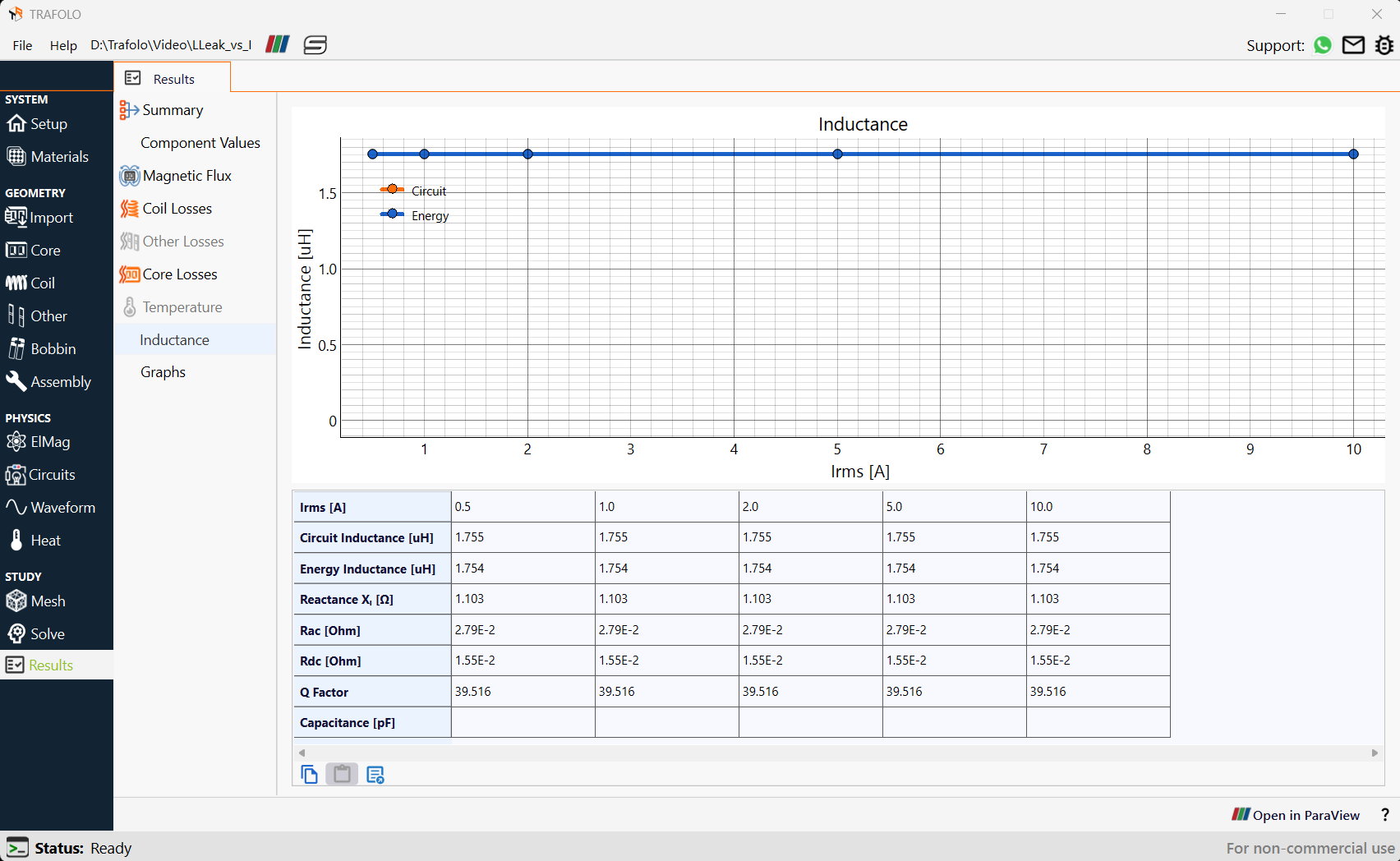
In the current range tested between 0.5 and 10 amperes, theleakage inductance does not show dependence on current. Reactance, AC Resistance, DC Resistance, and Q factor also remain constant in the tested range.
Magnetic Flux Distribution
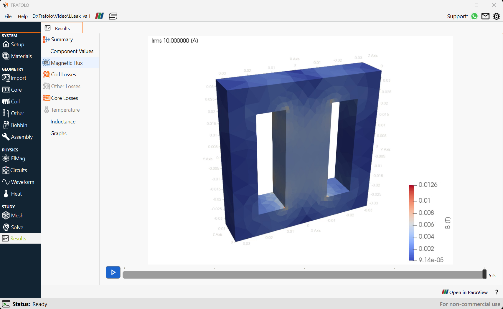
Magnetic flux amplitude in the core is significantly below its saturation point. This is because inductance is leakage-type and most of the magnetic flux remains concentrated between windings.
Analyzing Sweep Results in the ParaView tab
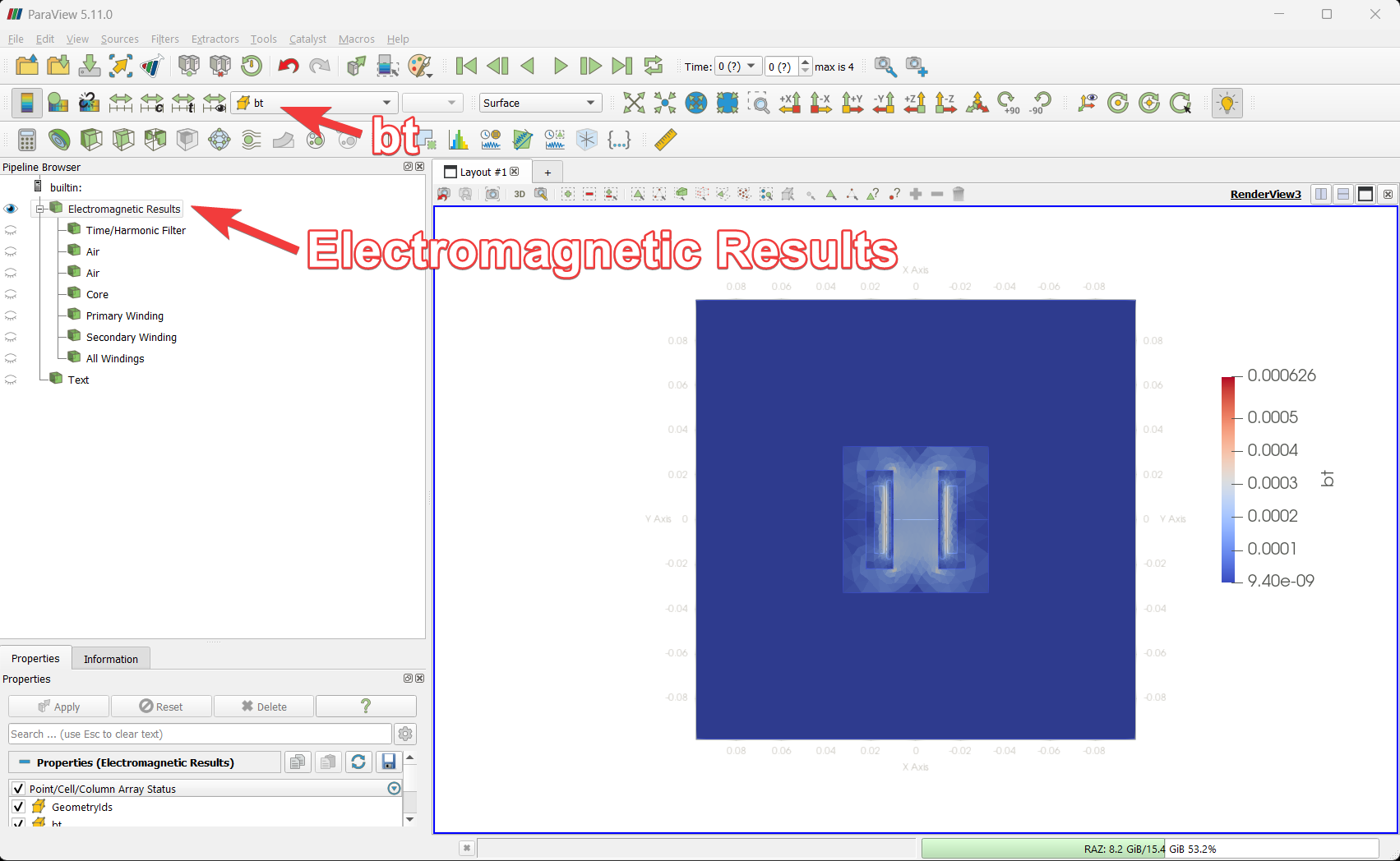
Further results can be analyzed by clicking the Open in ParaView button in the Results tab.
Enable the Electromagnetic Results eye icon and select bt to visualize detailed magnetic flux distribution. Since we have found leakage inductance magnetic flux distribution will be concentrated between windings.