LLC Coupled Transformer (with Inductor)
Introduction
A LLC coupled transformer is an integral part of electronics applications. This hybrid design is used in high-frequency converters as well as in magnetic integration in grid systems, and switch-mode power supplies. By combining the functionalities of a transformer and an inductor into a single core it reduces overall space by integrating two magnetic components thus making it an ideal choice for a compact and efficient system. Also, this model minimizes the cost of winding and core materials. It is more economical in large scale production. Further facilitates efficient energy transfer and increases leakage flux by sharing a common core. LLC Coupled transformer stores energy in the resonant inductor and works in LLC resonance. This guide offers a comprehensive and systematic approach for utilizing TRAFOLO to analyze the LLC Coupled transformer design. Additionally, TRAFOLO allows us to determine the temperature distribution, calculate core and copper loss in this design.
Model Description
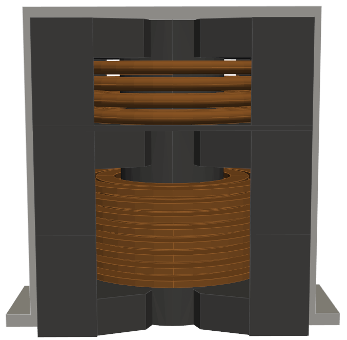
The LLC Coupled transformer is modeled with a single core. The wire used for the inductor's winding is Stranded & Litz, whereas the wire used for the Transformer is Massive Solid wire. Stranded& Litz wire is used to minimize skin and proximity effects at high-frequency applications. Massive solid wire is used to reduce the copper loss. The inductor is set in the upper part, and the transformer is set up in the down part where primary and secondary windings are interleaved. The windings are interleaved since the transformer windings help to reduce leakage inductance. An external structure is provided outside the core for support and heat sink. The model incorporates electromagnetic behavior under steady-state thermal conditions to accurately assess the model's performance. Further TRAFOLO also accurately predicts temperature, core loss, and coil loss simulations.
Modelling Instructions
Setup
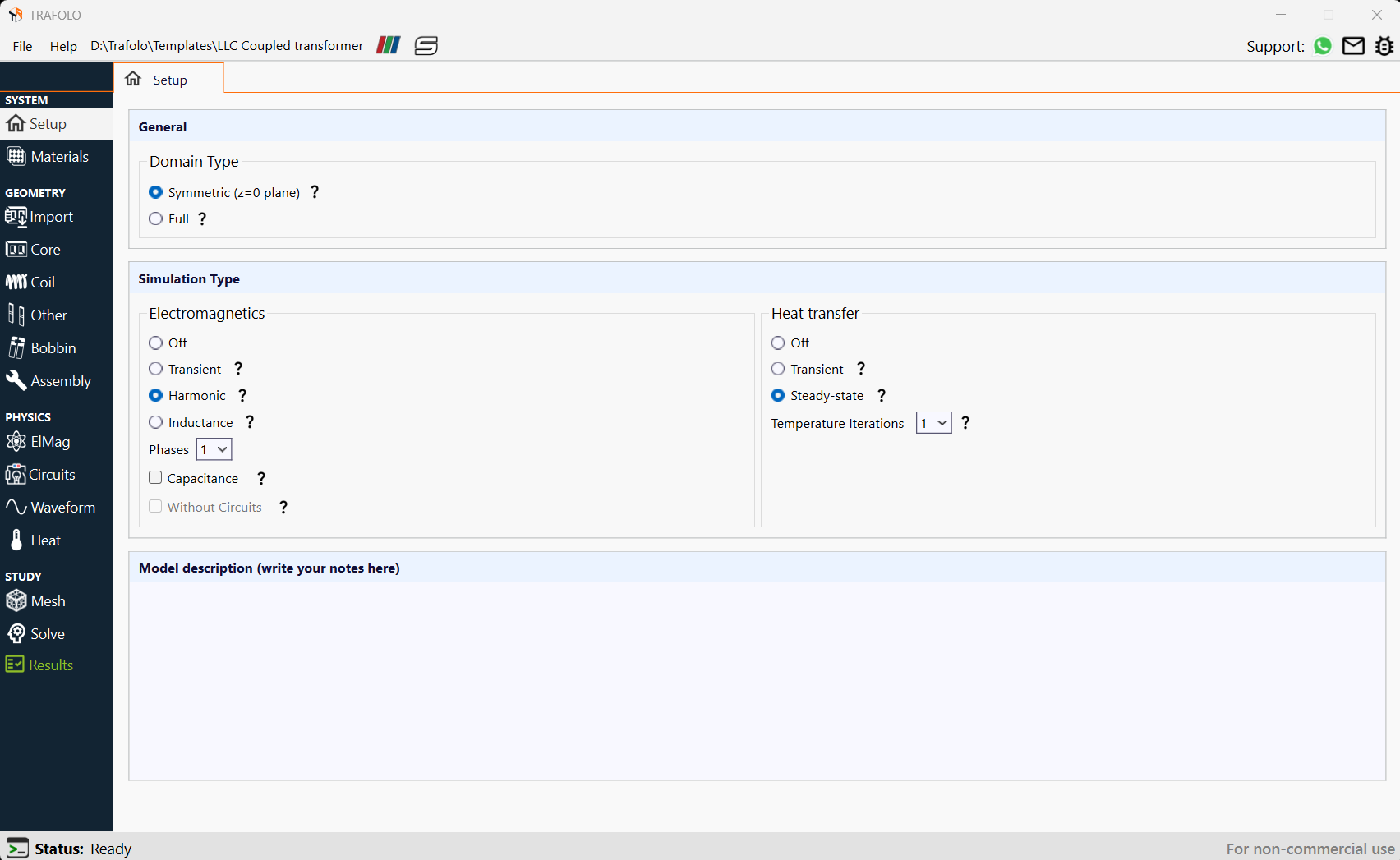
- From the Model Builder, click on the Setup tab.
- Locate the General section and set the Domain type as Symmetric due to its symmetry along the z-axis. This setting is beneficial for models with a plane of symmetry that divides the core and coil into symmetrical segments. This method ensures that the computed values reflect the complete system despite only modeling a symmetrical section.
- In the Simulation Type section, set Electromagnetics to Harmonic to show the presence of harmonics in the Transformer with Inductor.
- Additionally, Heat transfer should be set to Steady state since the transfer of heat remains in equilibrium.
Materials
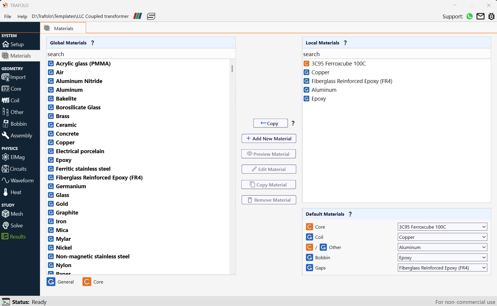
- From the Model Builder, select the Materials tab.
- From the Global Material section, select Copper and click the Copy button.
- Copy Aluminium, Epoxy, 3C95 Ferroxcube 100C, Fiberglass Reinforced Epoxy (FR4) from the Global Materials section to the Local Materials section in a similar manner.
- In the Default Materials section, select the material type for each component from the dropdown list as per the table below:
| Component | Core | Coil | Others | Bobbin | Gaps |
|---|---|---|---|---|---|
| Material type | 3C95 Ferroxcube 100C | Copper | Aluminium | Epoxy | Fiberglass Reinforced Epoxy (FR4) |
Core
- From the Model Builder, click on the Core tab.
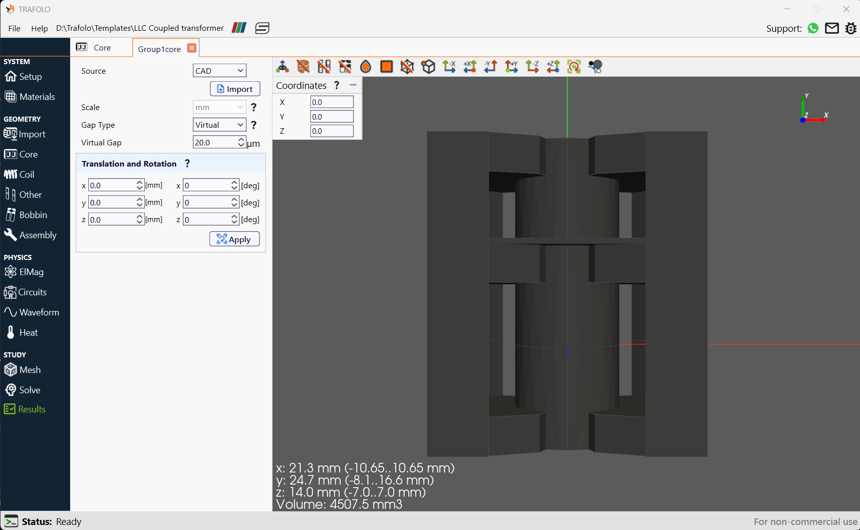
- Click the New Group button. The Group1core will open.
- Click the Open in new tab icon “⚙“ .
- From the Source dropdown list, select CAD.
- From the Scale dropdown list, select mm.
- From the Gap Type dropdown list, select Virtual.
- Set the Virtual Gap to 20μm. This represents a parasitic gap in the transformer, and the gap thickness in the inductor will be defined by a physical spacer with separate geometry.
Coil
- From the Model Builder, click on the Coil tab.
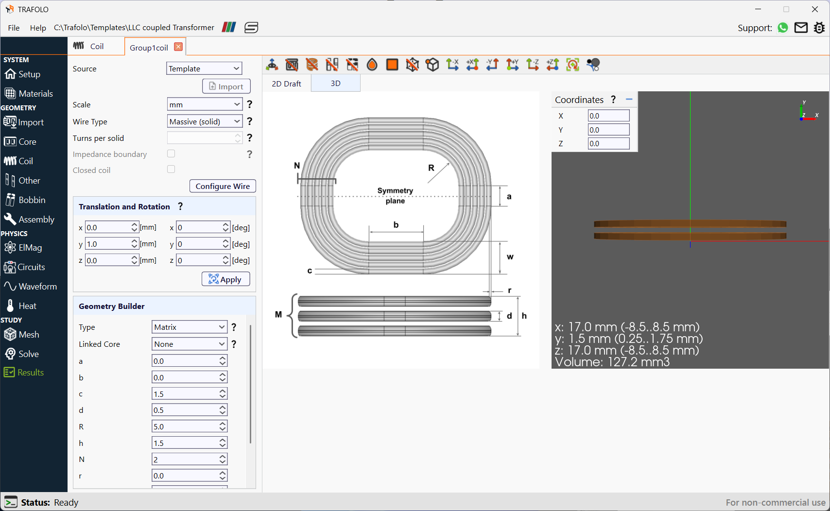
- Click the New Coil tab. The Group1coil will be added.
- Click Open in new tab icon “⚙“ . The Group1coil tab will open.
- From the Source dropdown list, select Template.
- From the Scale dropdown list, select mm.
- From the Wire Type dropdown list, select Massive(solid) wire.
- In Translation and Rotation set the y-axis to 1mm.
- In the Geometry Builder section set the Type to Matrix and the Linked Core to None. Enter the dimensions (mm) according to the table below:
| a | b | c | d | R | h | N | r | M | w |
|---|---|---|---|---|---|---|---|---|---|
| 0.0 | 0.0 | 1.5 | 0.5 | 5.0 | 1.5 | 2 | 0.0 | 2 | 3.5 |
- Click the Apply button.
- Similarly, create 3 more coils by copying Group1coil. Click the Copy icon “⧉”.
- Click Open in new tab icon “⚙“ and change the Translation for y-axis as follows:
| y-axis translation in mm | |
|---|---|
| Group2Coil | -1mm |
| Group3Coil | 3mm |
| Group4Coil | -3mm |
- Click the Apply button.
- Click the New Coil tab. The Group5coil will be added.
Group5coil will be a different type of coil. The first 4 coils are flat solid and Group5coil will be Standard Litz wire. - Click Open in new tab icon “⚙“ . The Group5coil tab will open.
- From the Source dropdown list, select Template.
- From the Scale dropdown list, select mm.
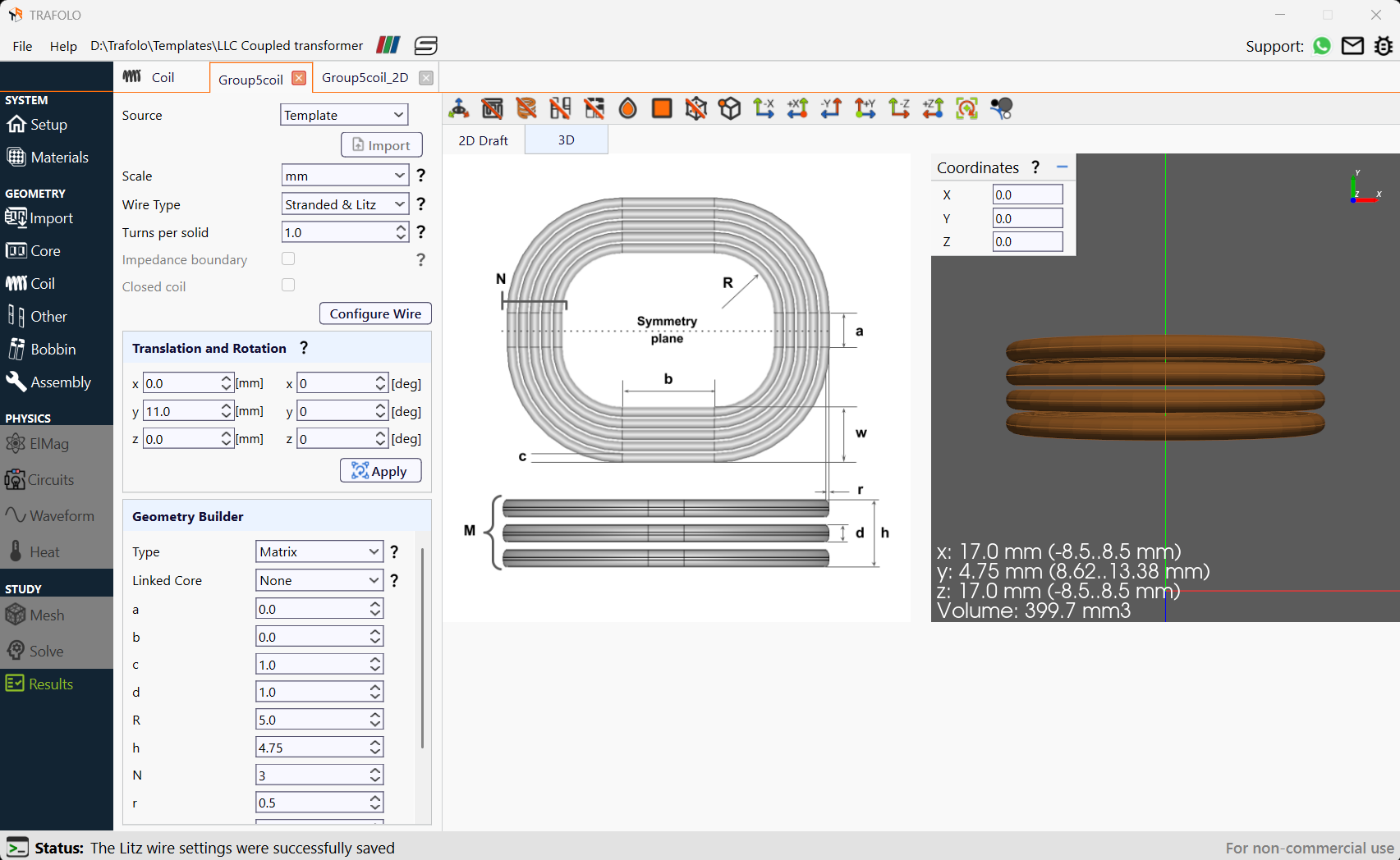
- From the Wire Type dropdown list, select Stranded and Litz wire and set turns per solid as 1.
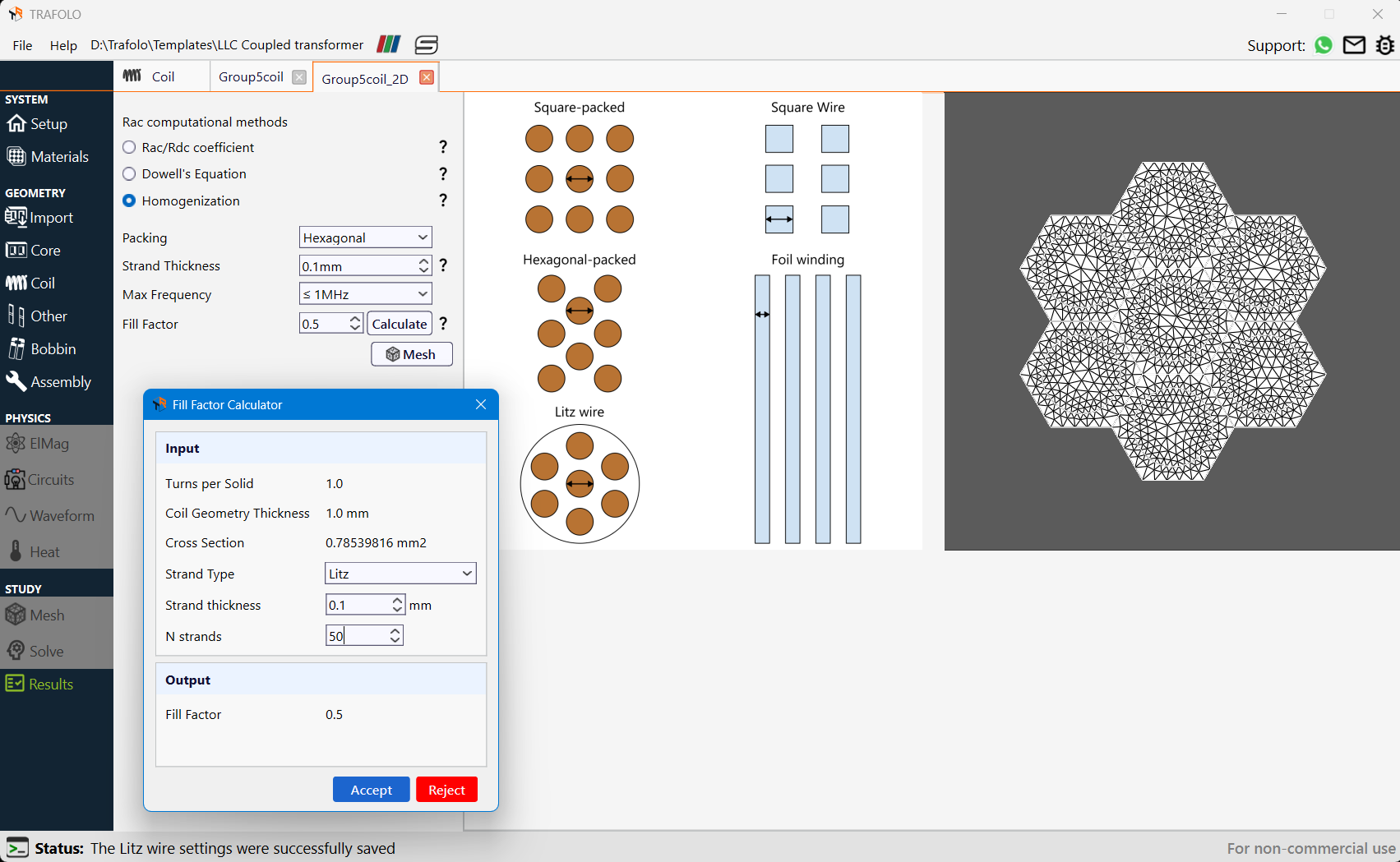
- Click on the Configure Litz wire tab.
- Choose Homogenization in Rac computational methods
- Set Packing as Hexagonal, strand thickness as 0.1mm, and maximum frequency.
Fill factor should always be less than 1.
- In Translation and Rotation set the y-axis to 11mm.
- In the Geometry Builder section set the Type to Matrix and the Linked Core to None. Enter the dimensions (mm) according to the table below:
| a | b | c | d | R | h | N | r | M | w |
|---|---|---|---|---|---|---|---|---|---|
| 0.0 | 0.0 | 1.0 | 1.0 | 5.0 | 4.75 | 3 | 0.5 | 4 | 3.5 |
- Click the Apply button.
Other
- From the model builder, click on the Other tab.
- Click the New Group tab. The Group1othergeometry will be added.
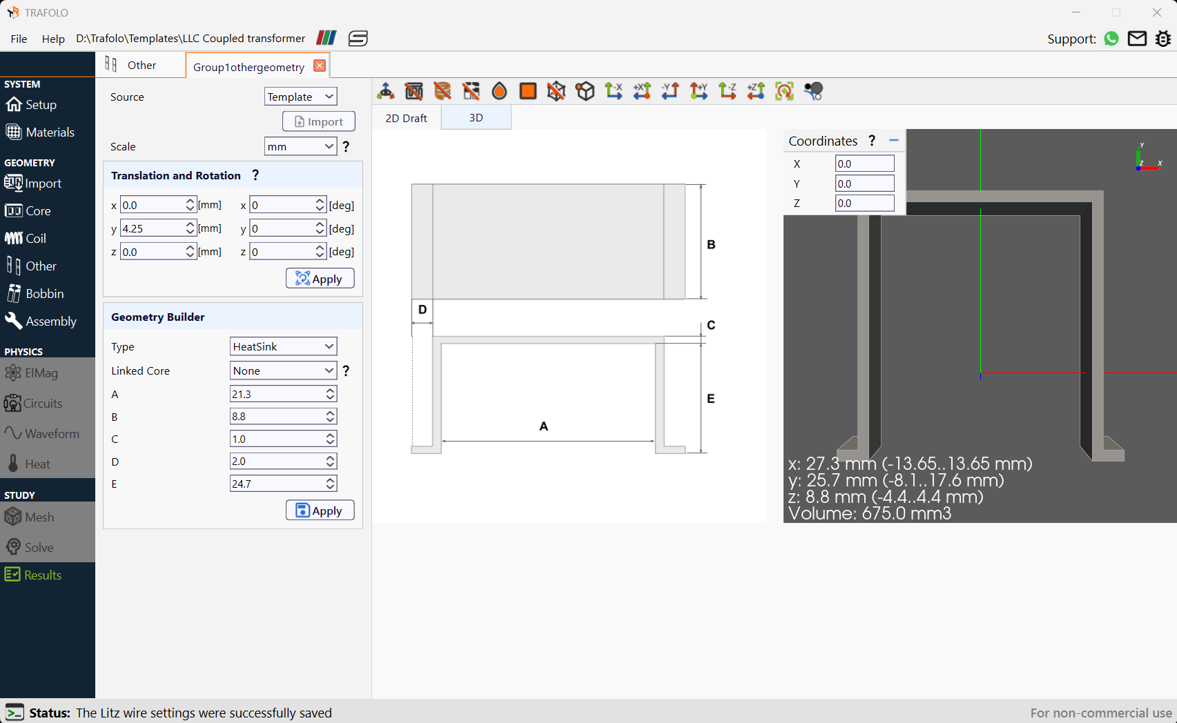
- Click Open in new tab icon “⚙“ . The Group1othergeometry tab will open.
- From the Source dropdown list, select Template.
- From the Scale dropdown list, select mm.
- In Translation and Rotation set the y-axis to 4.25mm.
- In the Geometry Builder section set the Type to Heatsink and the Linked Core to none. Enter the dimensions (mm) according to the table below:
| A | B | C | D | E |
|---|---|---|---|---|
| 21.3 | 8.8 | 1.0 | 2.0 | 24.7 |
- Click the Apply button.
Bobbin
- From the model builder, click on the Bobbin tab.
- Click the New Group tab. The Group1bobbin will be added.
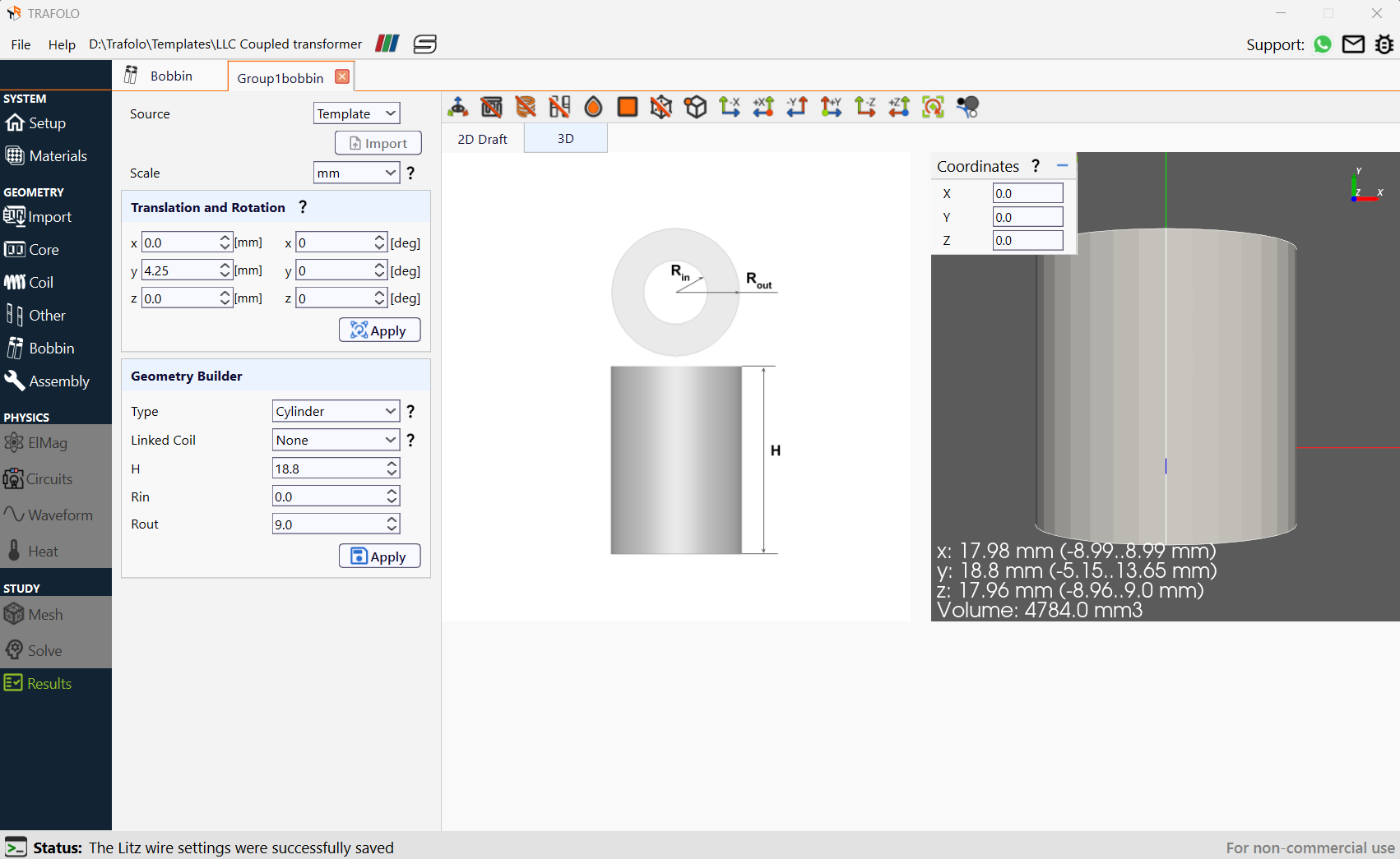
- Click Open in new tab icon “⚙“ . The Group1bobbin tab will open.
- From the Source dropdown list, select Template.
- From the Scale dropdown list, select mm.
- In Translation and Rotation set the y-axis to 4.25mm.
- In the Geometry Builder section set the Type to Cylinder and the Linked Coil to none. Enter the dimensions (mm) according to the table below:
| H | Rin | Rout |
|---|---|---|
| 18.8 | 0.0 | 9.0 |
- Click the Apply button.
Assembly
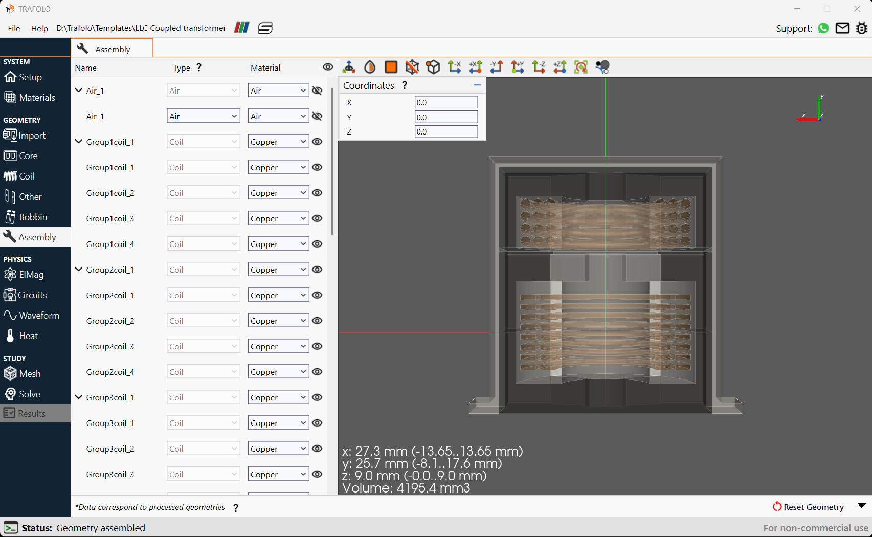
- Click the Assembly tab under the Model Builder.
- Since a core with a spacer is used it is ensured that materials are not placed in gap.
- Click the Assemble Geometry button. The assembled geometry will be displayed.
ElMag
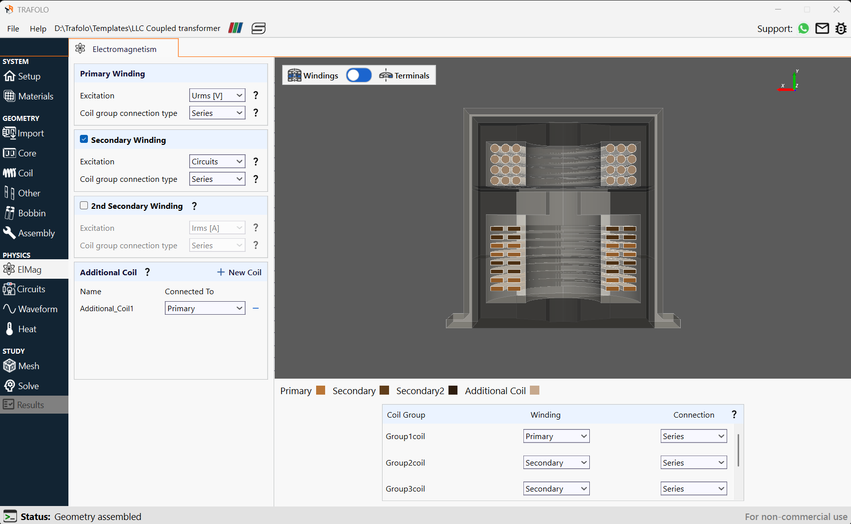
- Open the ElMag tab from the Model Builder.
- Locate the Primary Winding section.
- Set the Excitation to Urms [V] and the Coil group connection type to Series from the dropdown list.
- Enable the Secondary Winding by checking the box.
- Set the Excitation to Circuits and the Coil group connection type to Series from the dropdown list.
- Further, Enable the 2nd Secondary Winding and set excitation to Irms [A] and the Coil group connection type to Series from the dropdown list.
- Add an Additional Coil1 connected to the Primary.
- The transformer has vertically interleaved windings that for a solid wire might be easier to produce while keeping some leakage inductance.
- Set the Winding and Connection for each coil group as per the table below:
| Coil group | Winding | Connection |
|---|---|---|
| Group1coil | Primary | Series |
| Group2coil | Secondary | Series |
| Group3coil | Secondary | Series |
| Group4coil | Primary | Series |
| Group5coil | Additional_Coil1 | Series |
Circuits
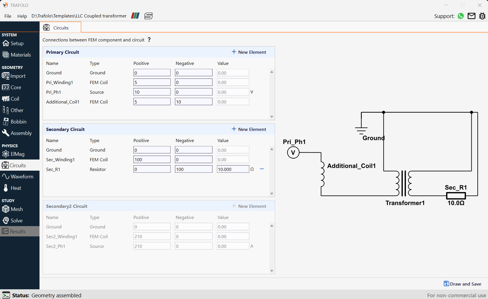
- Select the Circuits tab from the Model Builder.
- The user sets up the circuit.
- It consists of a primary voltage source connected to the primary side of Transformer1. An Additional_Coil1 is also connected to the primary side of the transformer.
- A resistance of 10.0Ω is connected across the secondary side of the transformer
- Click the Apply button.
Waveform
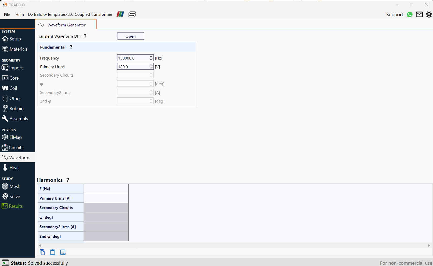
- From the Model Builder, select the Waveform tab.
- Specify the Fundamental frequency and the corresponding voltage excitation. In this case, the Frequency is 150000.0 [Hz] with a Primary Urms of 120.0 [V].
Heat
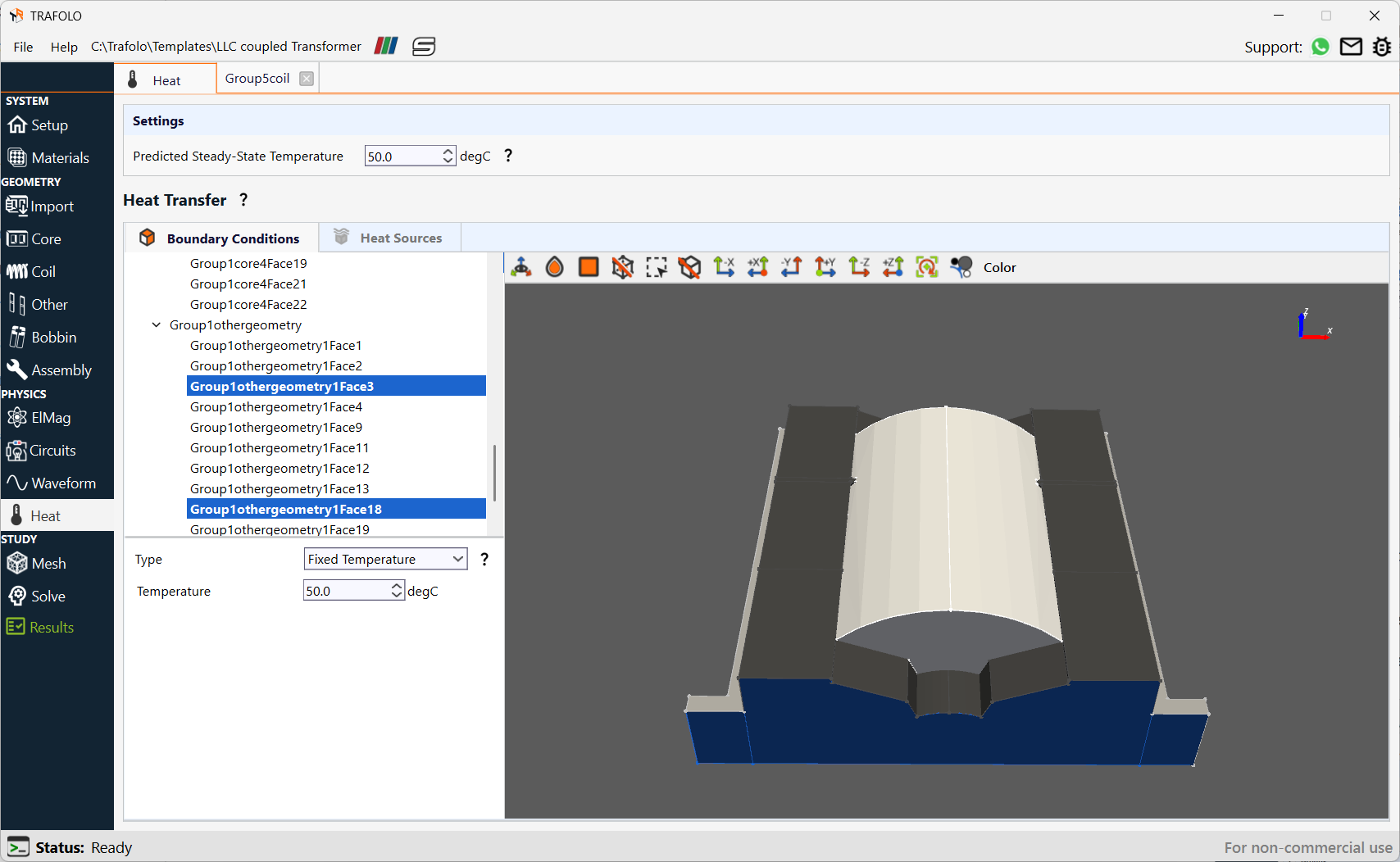
- From the Model Builder, click the Heat tab.
- Set the Predicted Steady-State Temperature in the Settings section to 50 °C The initial temperature is set based on prediction.
- Locate the Boundary Conditions section.
- Click the Geometry.
- In the Type list, select Convection.
- In the External temperature (deg C) text field, type 50.
- In the Heat transfer coefficient (W/m2/K) text field, type 10.0.
- Select the 3 bottom faces of the structure from the model, set the Type as Fixed Temperature, and temperature is set as 50 (degC).
The bottom 3 faces represent the mounting surface of the transformer, and they remain at a fixed temperature since ideally the mounting object acts as a heat sink .
Mesh
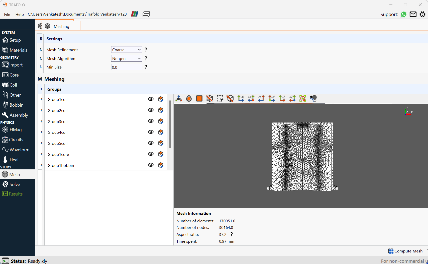
- From the Model Builder, click on the Mesh tab.
- Under the Settings section, from the Mesh Refinement dropdown list, select Coarse.
-
Also, choose the Mesh Algorithm for Netgen.
-
Click the Evaluate Mesh button followed by the Compute Mesh button.
Solve
- From the Model Builder, click on the Solve tab.
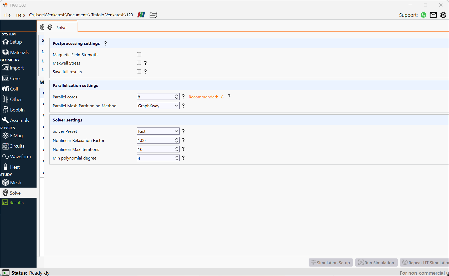
- Click on the Simulation Setup button followed by the Run Simulation button.
Result and Discussion
- From the Model Builder, click on the Results tab.
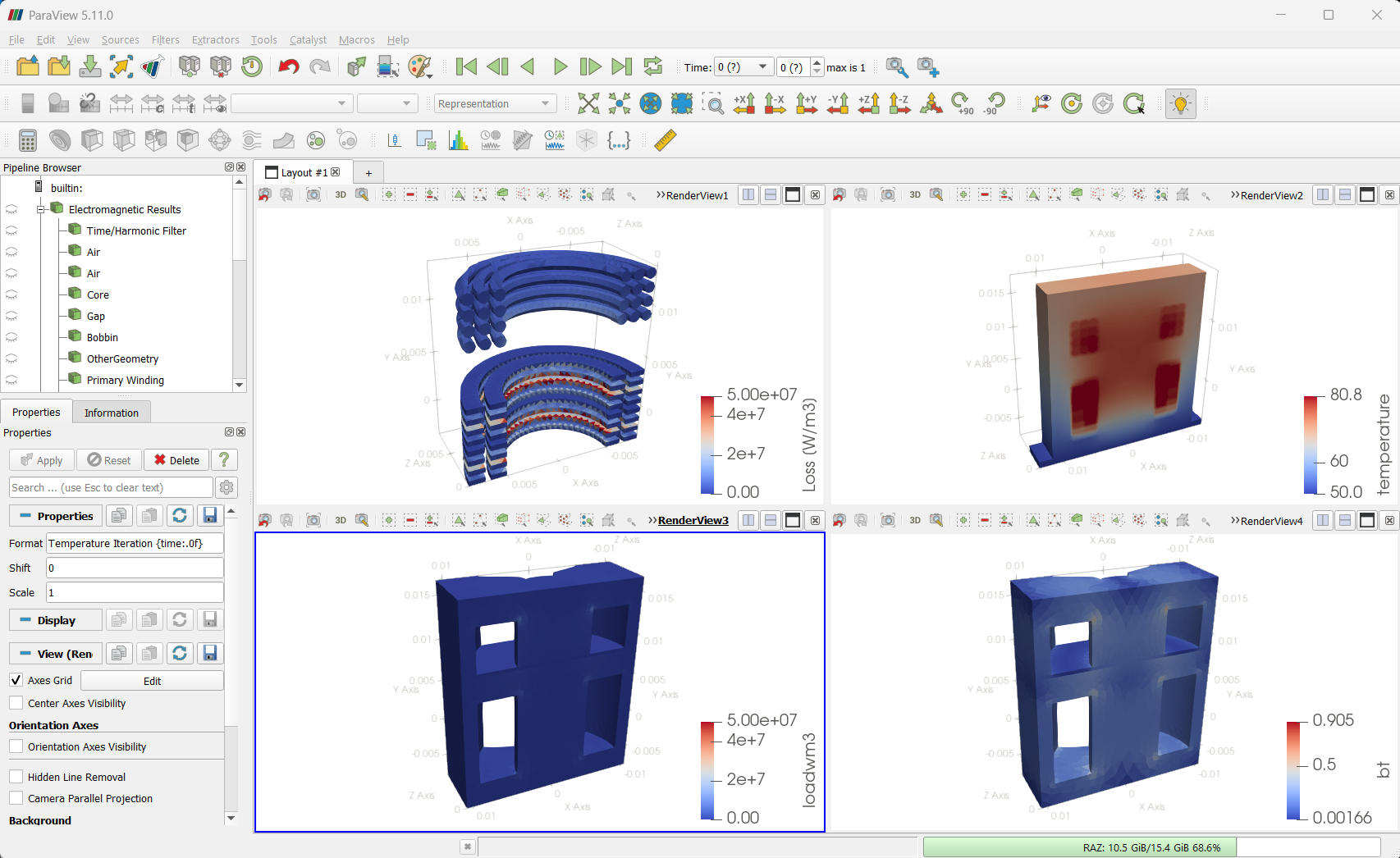
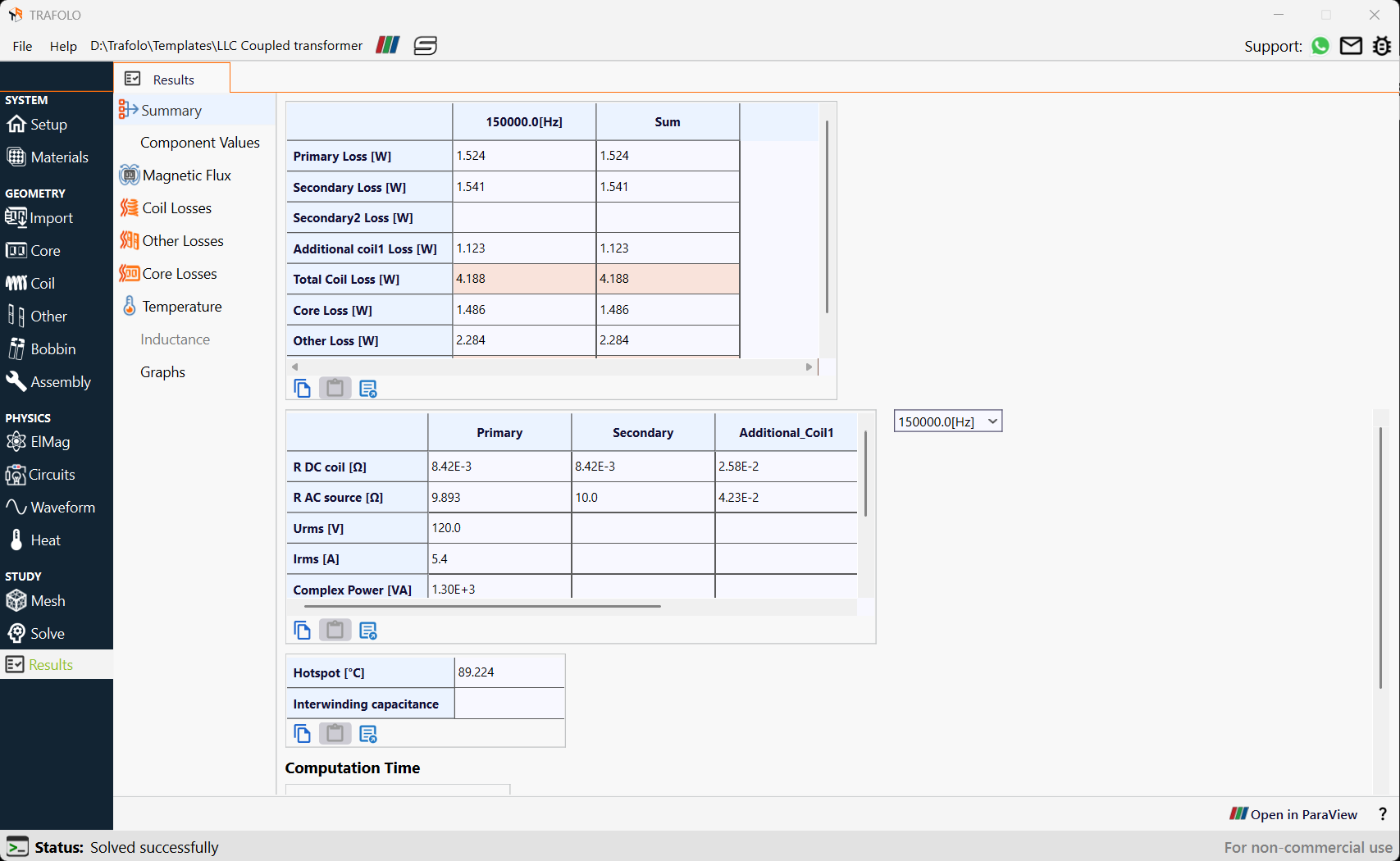
- Click on the Summary tab to obtain the average values of losses and electrical parameters at 150000 Hz, as well as the overall hotspot temperature.
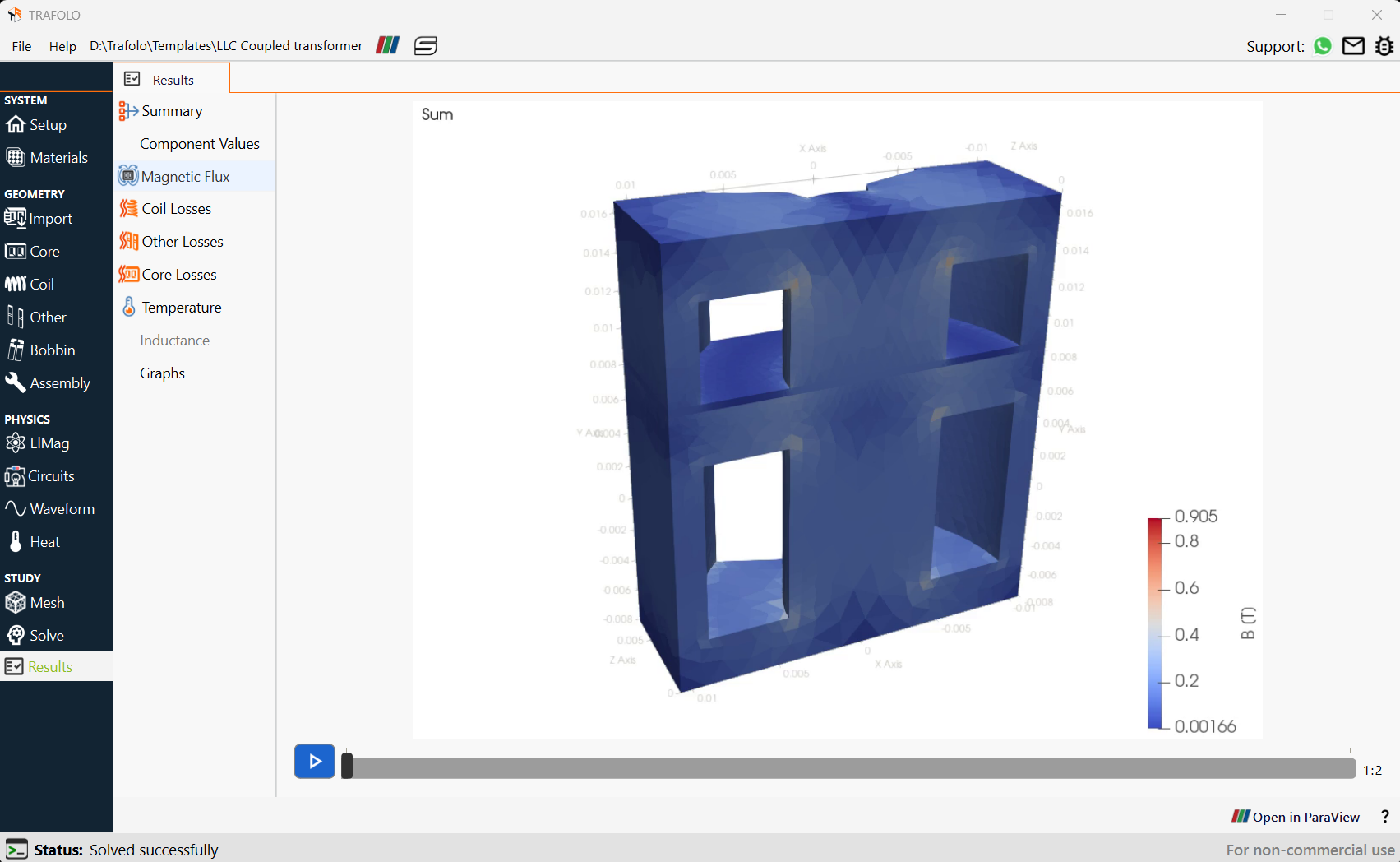
- The magnetic flux density distribution indicates that flux tends to concentrate near edges
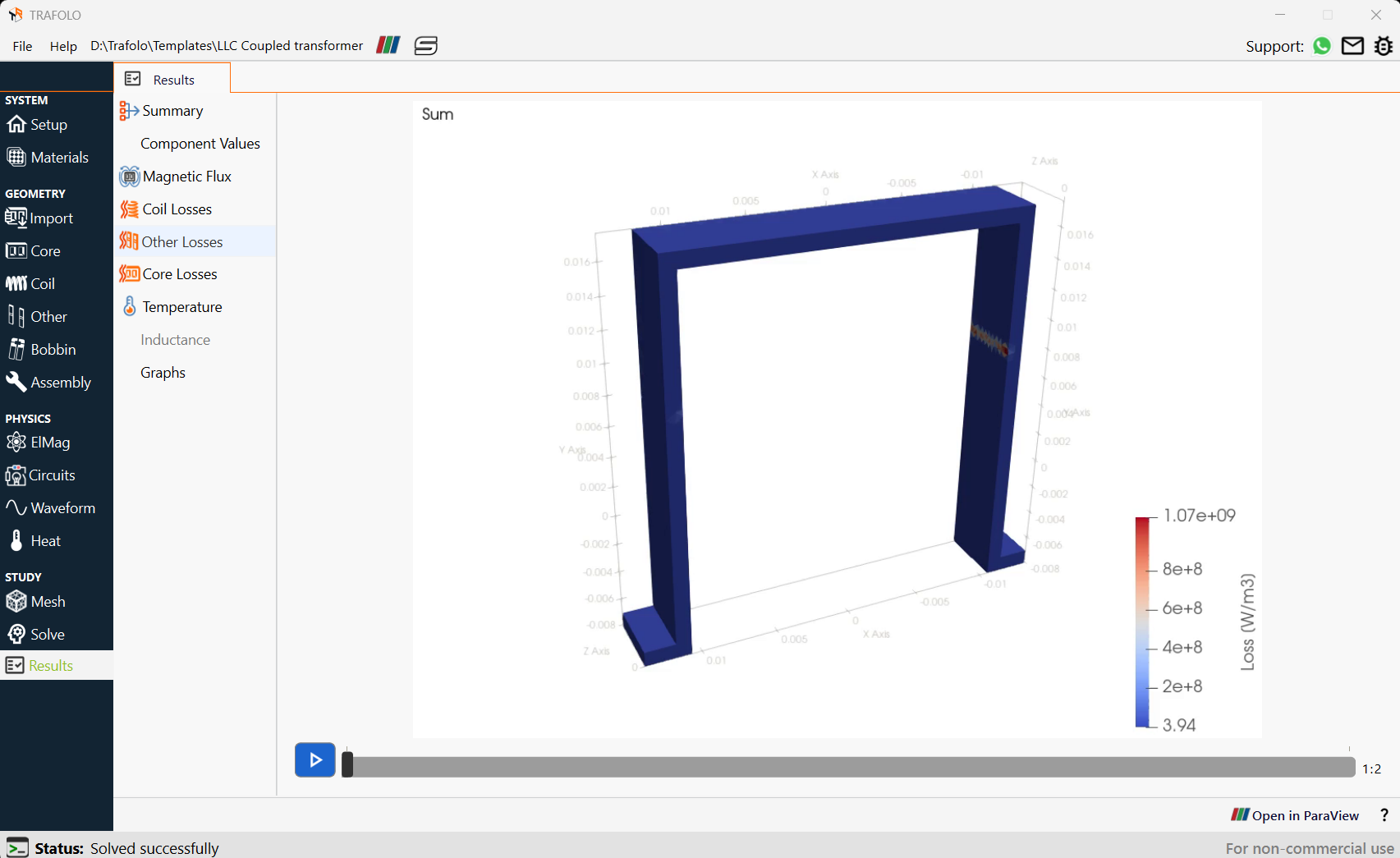
Losses occur due to leakage flux (due to flux) near the heatsink which is made of aluminum. As a result, eddy current is generated in areas near the gap.
The surface temperature distribution indicates heating in the windings of the LLC Coupled Transformer, with a hotspot of 89.2°C in their central region. Implementing a heat sink at the bottom of the core effectively cools the LLC Coupled transformer, thereby maintaining the temperature well below critical levels.
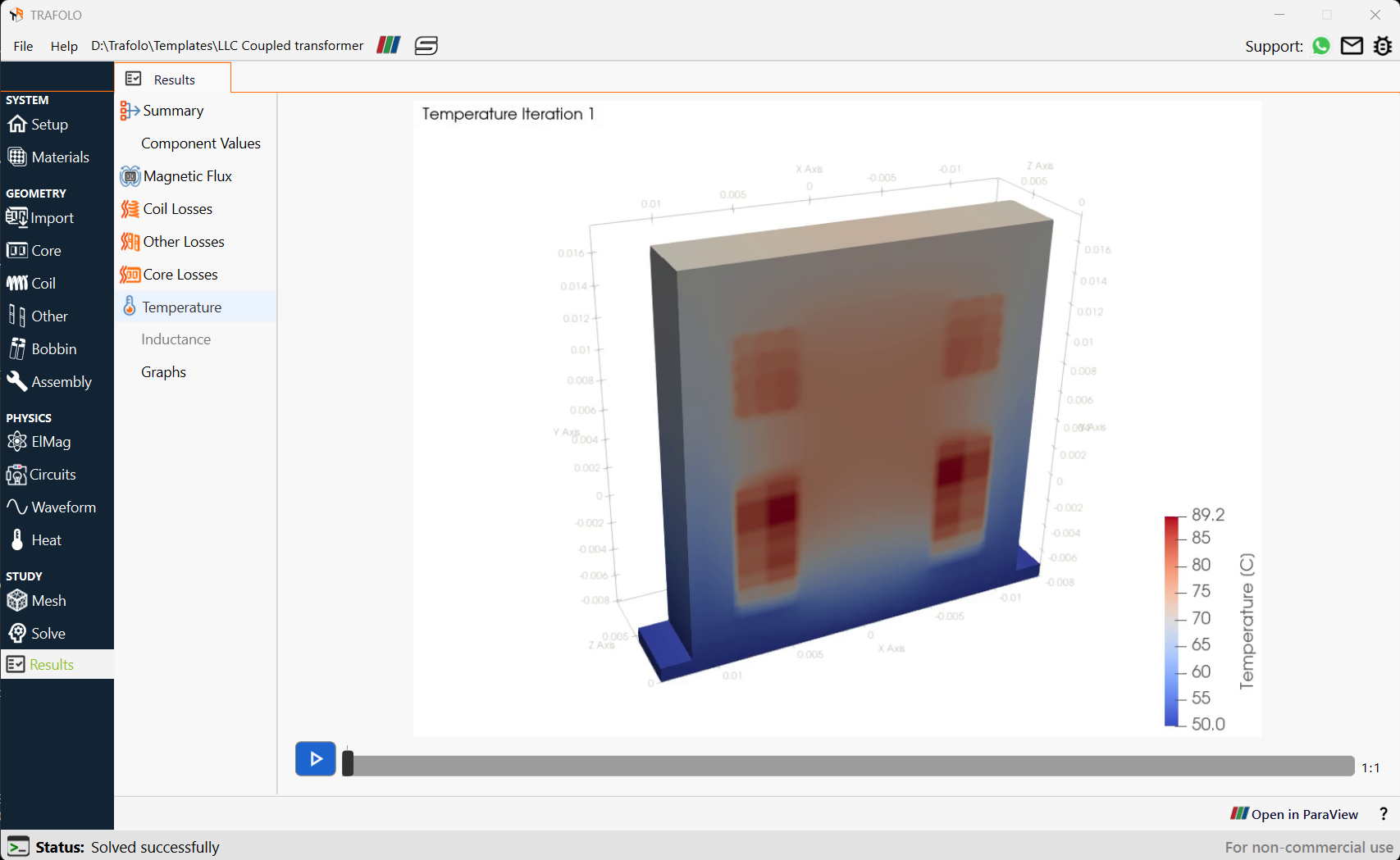
- Click the Open in ParaView button to open simulation results in post-processing software. It allows manipulation with results, changing color schemes, making slices, and doing any other manipulations with results.
ParaView has been used for detailed visualization and analysis of the flux density, temperature, and loss distribution, as shown in the accompanying figures.