Circuits
By default, TRAFOLO will set up a circuit, connecting windings to their respective sources and ground. Further, the setup can be enhanced by adding linear elements (L-R-C), configuring loads as impedances, solving resonant LLC converters, or establishing delta, parallel, or series connections between windings.
TRAFOLO uses Circuit Netlist to describe how circuit components are connected. Components sharing the same indexes are connected.
Converting electrical scheme into Netlist
In this case, we will set up a circuit consisting of a power source, transformer, and resistor for the autotransformer case.
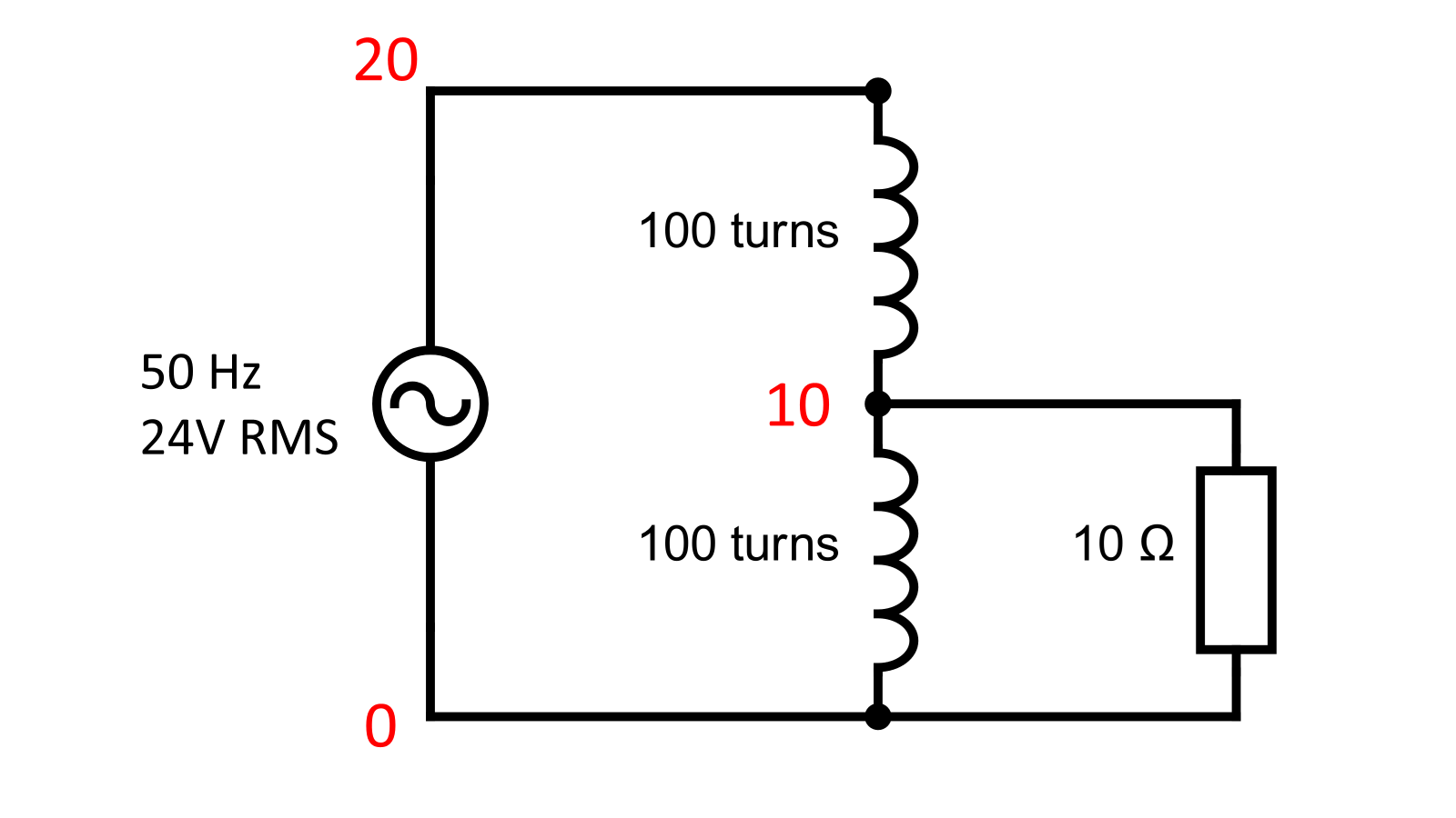
First, choose a reference point for the ground. Usually, that is one of the power source terminals. In TRAFOLO, the ground always has an index of 0. In this case the ground is connected to the negative terminal of the source, secondary winding of the transformer and negative terminal of the resistor load.
Next, we have two more connection points:
- Between positive source terminal and primary winding.
- Between primary and secondary windings and a resistor.
For these points, we will choose indexes 20 and 10, respectively. The selection of index numbers is arbitrary as long as they are unique.
Adding New Elements
By default, TRAFOLO will add all windings and sources (primary, secondary, 2nd secondary) defined in ElMag to the circuit table.
Add all the missing components to the Circuit Netlist. For the autotransformer, we only need to add a resistor connected to the secondary winding. Click on New Element and select Resistor.
Setting the Circuit Netlist
By default, all grounds in Primary and Secondary are set to the 0 index. This ground is numerical and has no impedance, meaning no physical current flows between primary and secondary. For numerical reasons (the solution should be unique), we must fix the potential at some point.
The setup for the autotransformer is shown in the figure given below. The primary source, winding terminals, and resistor connections are assigned specific indexes. The resistor is set to a defined value, and the configuration is finalized before the user clicks on the Draw and Save button to draw the circuit.
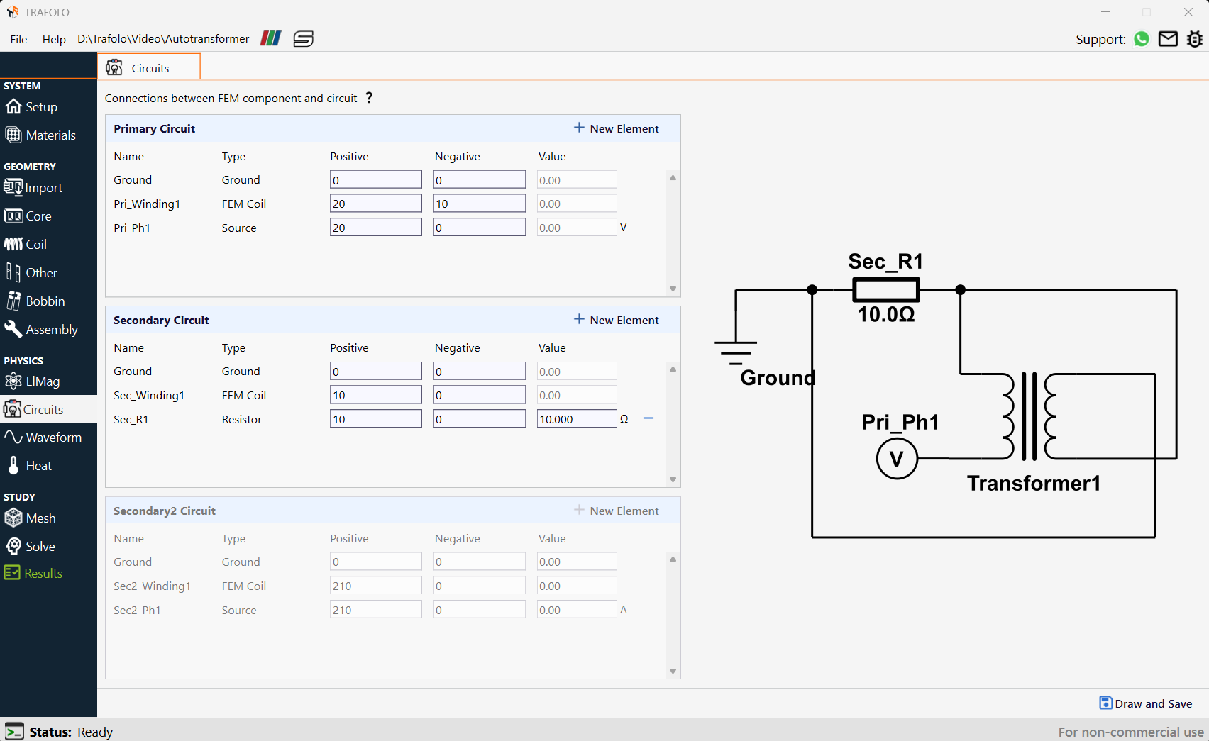
Note that the voltage source has only one terminal. This is because TRAFOLO sets the source as a positive terminal while the ground acts as a negative terminal.
Analyzing Circuit Results
Each circuit component, including FEM windings, has voltage and currents being solved. For harmonic simulations, currents and voltages will be represented as complex numbers for each solved frequency, while in transient simulations, those will be represented as time series.
To see these values, head to the Results tab.
Winding Components
Under the Component Values tab, it provides voltages and currents for individual winding geometries and winding groups. Complex voltages and currents are given for individual winding geometries.
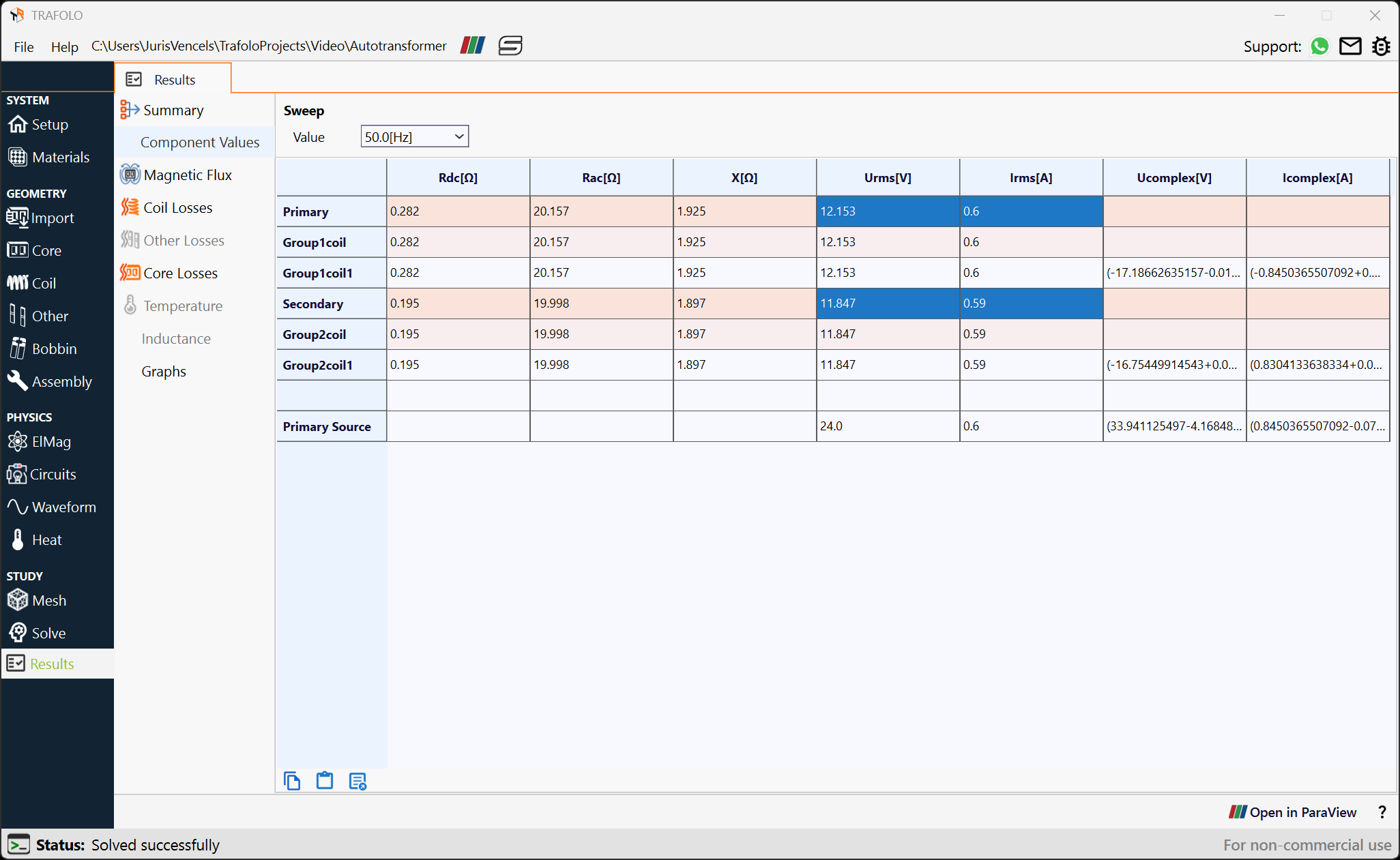
All Component Results
In the Graphs section, voltages and currents for all circuit components can be seen and compared. Here, i_component and v_component correspond to the current and voltage of the winding geometry with a specified index. Note that if the winding has multiple geometries (separate turns), each turn counts as a component, and values are given.
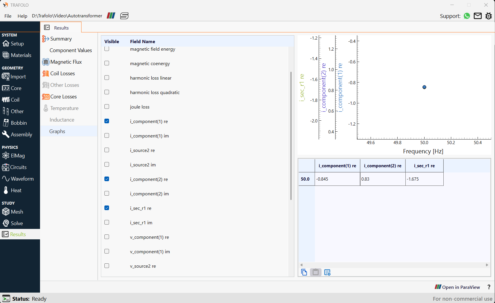
As can be seen, the current in the resistor is equal to the sum of the current in primary and secondary.
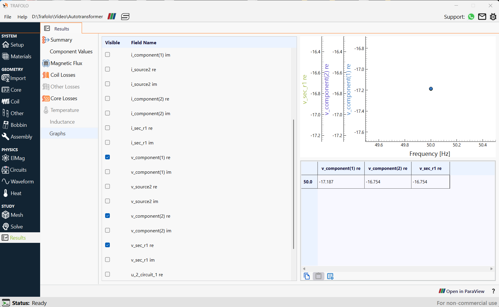
The voltage amplitude in the primary is greater than the secondary, but the voltage in the secondary is equal to the voltage across the load. This is the expected result for a non-ideal transformer.