Inductance (frequency and excitation sweeps)
Inductance sweep conducts multiple harmonic simulations to calculate inductance, reactance, Q-factor, losses, and other related parameters across different currents, voltages, or frequencies.
Model Setup
To enable inductance calculation, select Inductance Simulation Type in the Setup tab.
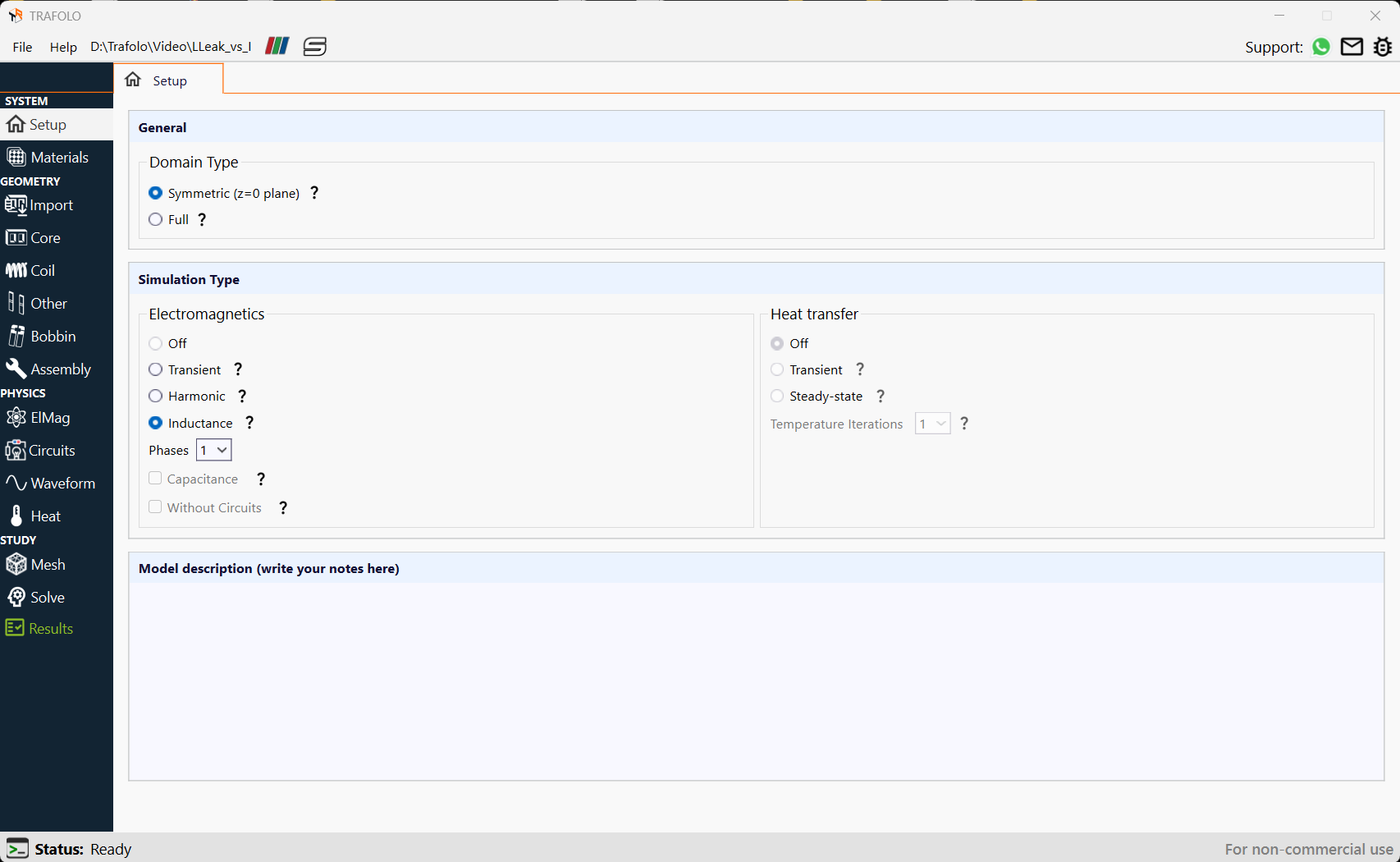
Setting Inductance Type
For inductors, select Excitation as Voltage or Current. It will be used to calculate magnetizing inductance.
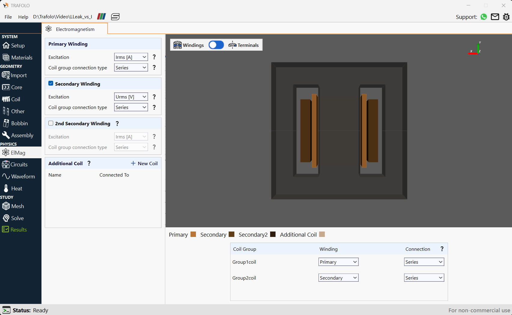
For transformers, enable Secondary Winding and the 2nd Secondary Winding (if needed), and set Winding types and connections accordingly. Magnetizing or Leakage inductance will be calculated depending on the Secondary Winding Excitation type:
- If Urms [V] is selected and set to 0, Leakage Inductance will be calculated.
- If Irms [A] is selected and set to 0, Magnetizing Inductance will be calculated.
- If Circuits is selected, the inductance type will depend on the impedance that the user sets.
Setting Sweep Parameter Values
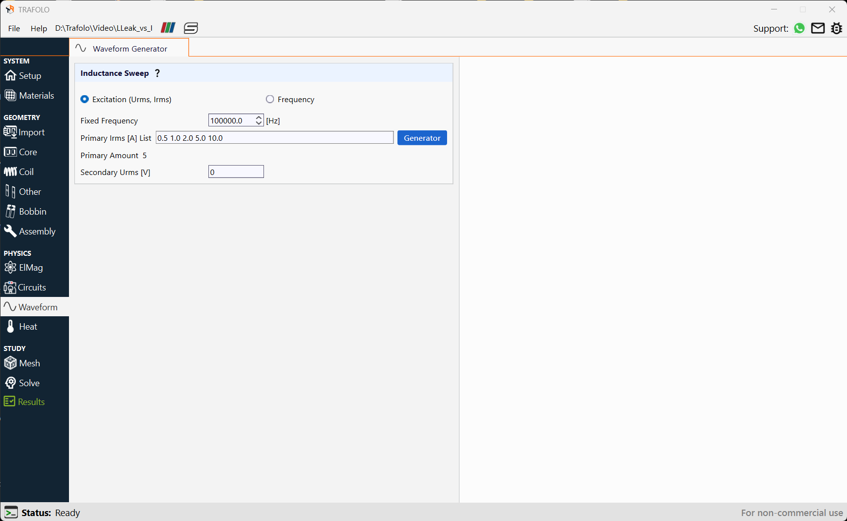
A parametric sweep can be set either for Excitation or Frequency.
Note that each value in the sweep corresponds to a separate simulation, which increases the total simulation time. A common mistake is setting up a sweep with hundreds of points when just a few dozen are sufficient to capture significant changes in inductance. As a starting point, we often use near-exponential distribution, for example [1, 2, 5, 10, 20, 50, 100] to reduce number of simulations while resolving a wide value range.
The following example demonstrates a fixed frequency with a primary current sweep, where the secondary voltage is set to 0V. With no impedance on the secondary terminals, the induced current in the winding opposes the primary current. This setup effectively models the leakage inductance.
Analyzing Results
Numerical results
Inductance is calculated using two methods:
- The circuits method involves dividing complex voltage by complex current to extract impedance.
- The energy method involves integrating magnetic fields and dividing by the square of the primary current.
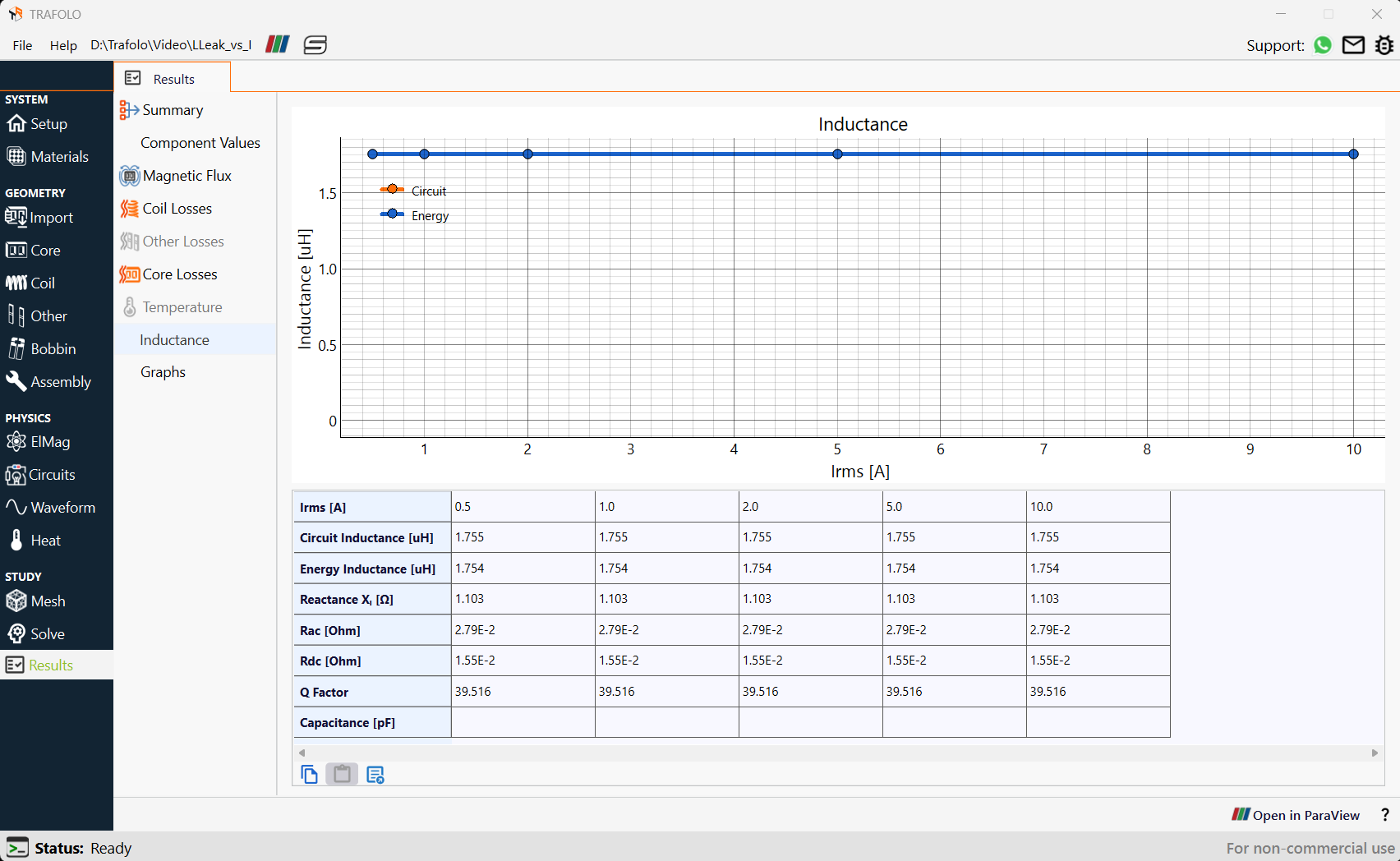
In the example below, the current ranges between 0.5 and 10 amperes, and theleakage inductance does not show dependence on the current. Reactance, AC Resistance, DC Resistance, and Q factor also remain constant in the tested range.
Magnetic Flux Distribution
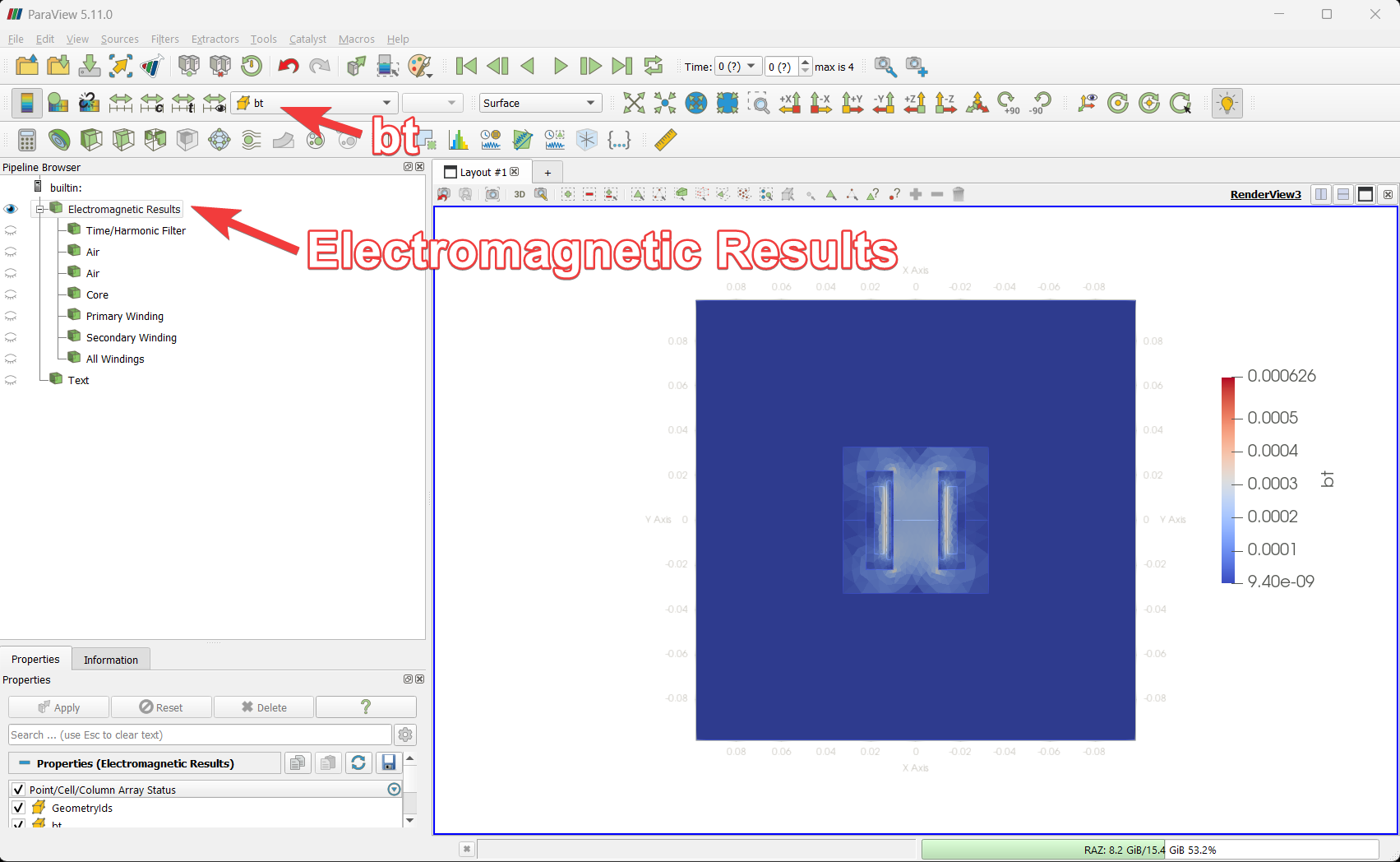
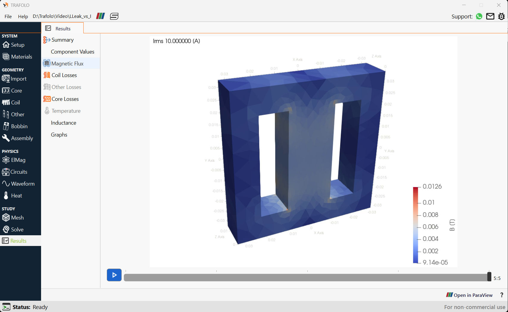
The magnetic flux density in the core and gap can be seen in the Magnetic Flux section of the Results tab. This is because inductance is leakage-type, and most of the magnetic flux remains concentrated between windings.
Analyzing Sweep Results in the ParaView tab
Further analysis can be performed using the Open in ParaView button in the Results tab.
To visualize the magnetic flux distribution, enable the Electromagnetic Results filter and select bt in the ParaView tab. Since leakage inductance has been determined, the magnetic flux will be concentrated between the windings.