Importing CAD Geometries
In TRAFOLO, there are two ways of importing geometries:
- Importing full geometries using the Import tab. It allows partitions and multiple files to be imported simultaneously. The user can then group or fuse geometries before assigning them to Geometry types.
- Importing individual geometries directly through Geometry group settings. In such a way, only one file can be imported at once, but this option provides more tools and settings for geometry manipulation after the import.
Importing through the Import tab
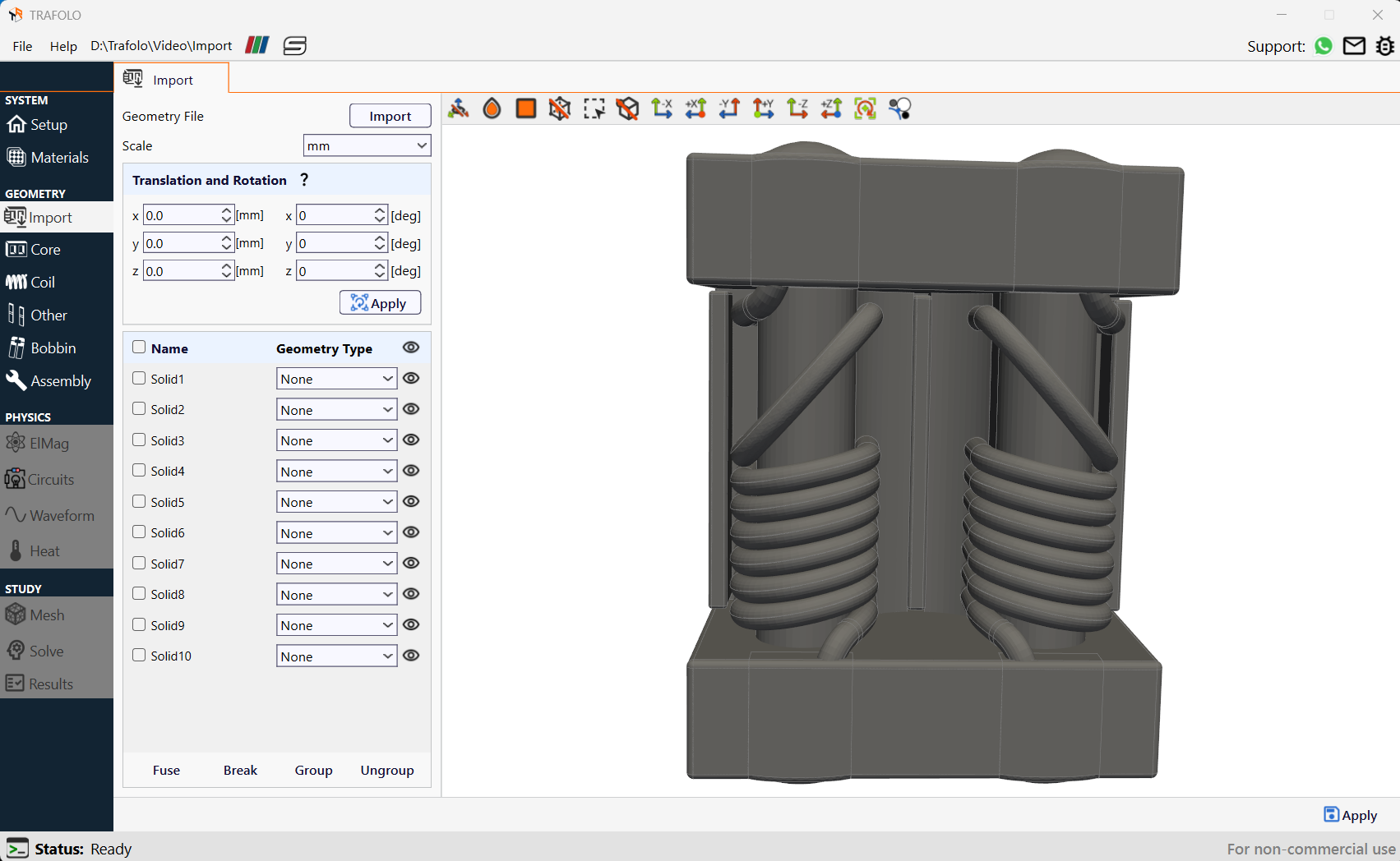
Consider a choke from Bel Transformer as a demonstration. It has two windings to suppress common mode noise in electronic devices. The model 3D geometry: SPDL975WM-500-2P-T.
- Click Import to select the Geometry File for import.
- Select one or multiple IGES or STEP files.
Fusing Geometries
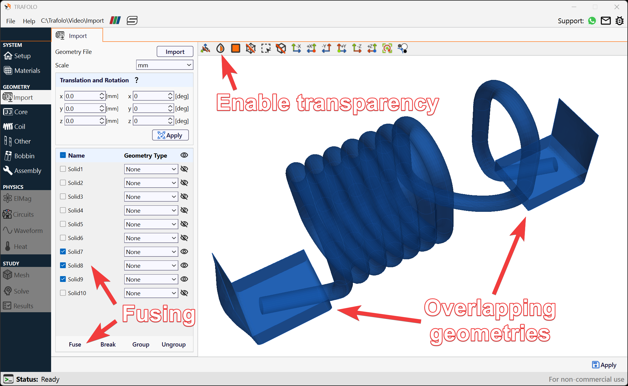
In this example, the imported geometry consists of overlapping windings and solder. TRAFOLO requires each winding or turn to be represented as a single geometric object. This is related to the automated terminal identification and setup in later stages.
You can enable transparency on the preview toolbar to identify overlapping geometries better.
- Select all parts of the same component (e.g., a coil). To select multiple geometries, use multiselection by holding Shift and clicking on geometries.
- Fuse them using the Fuse button.
Grouping Geometries
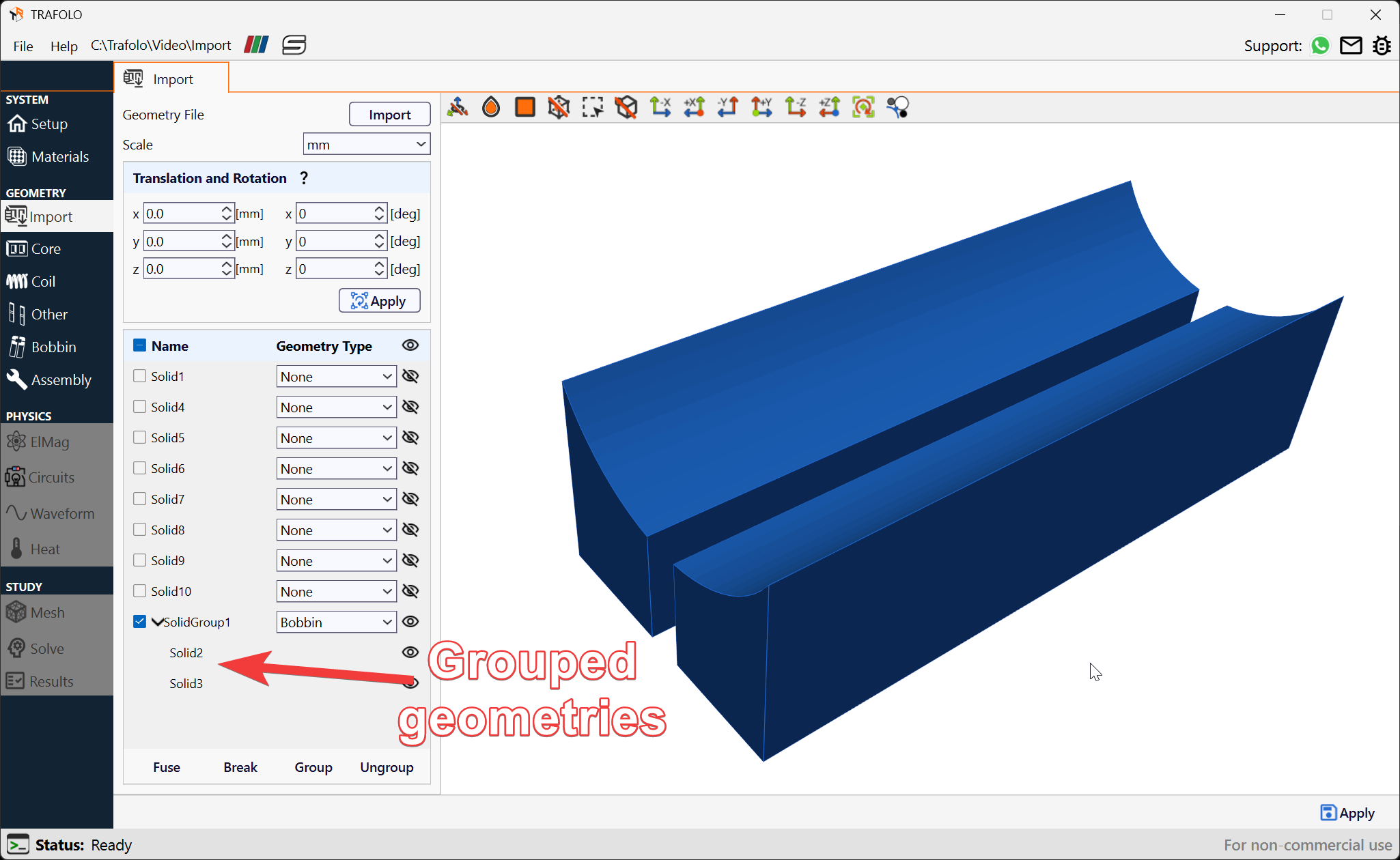
Geometry groups reduce the number of objects the user should interact with and allow settings to be applied to multiple objects simultaneously.
- Select geometries to be grouped. To select multiple geometries, use multiselection by holding Shift and clicking on geometries.
- Click on the Group button.
Assigning Geometry Types
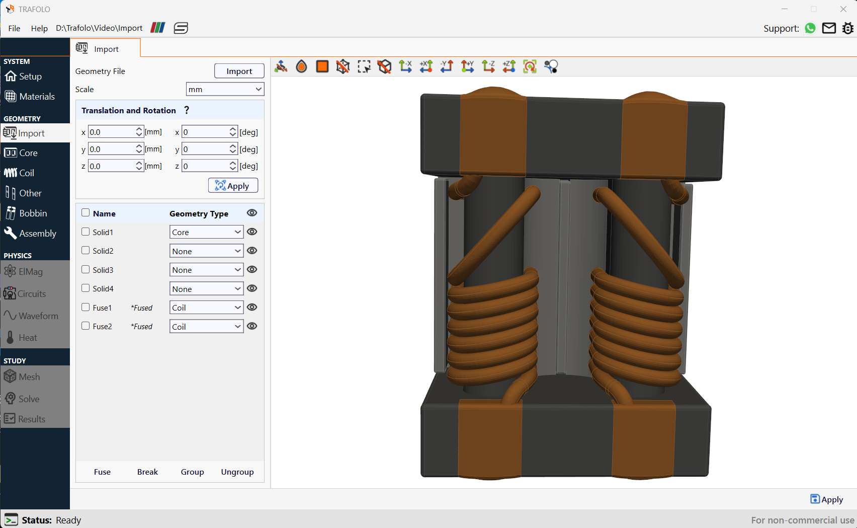
- Set the Geometry Type for the Core (including gaps), Coil, Other, and Bobbin geometries.
- Geometries that are unimportant for the simulation's accuracy are kept as None. Those will not be transferred to the Geometry module.
Transferring Imported Geometries to the Geometry Module
- Once all geometry types are set, click Apply (located in the bottom-right corner) to copy geometries to the corresponding Geometry tab.
- Geometry with the assigned Core type will be transferred to the Core tab as a geometry group.
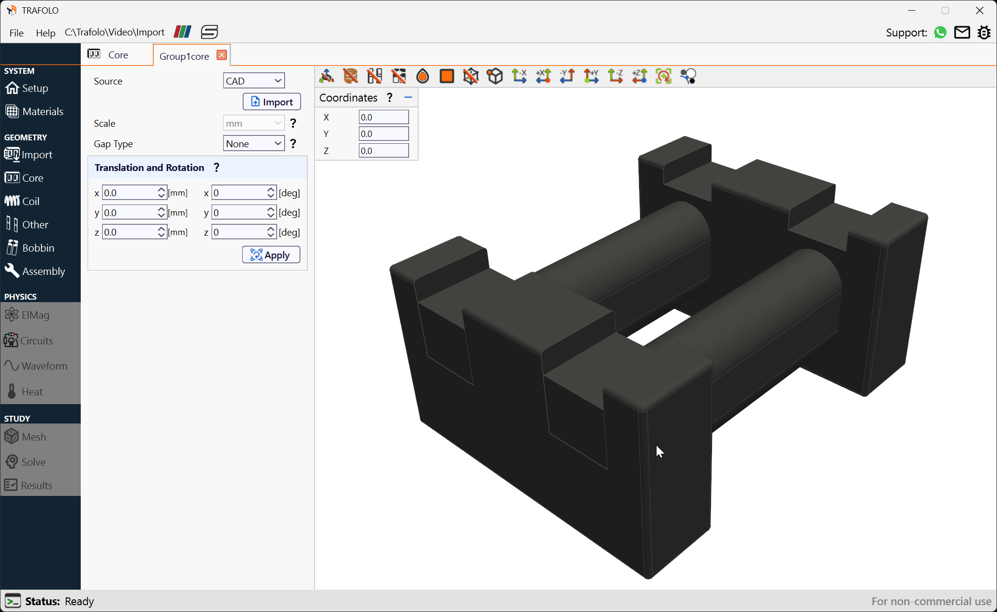 3. Two windings will appear as geometry groups in the Coil Groups list.
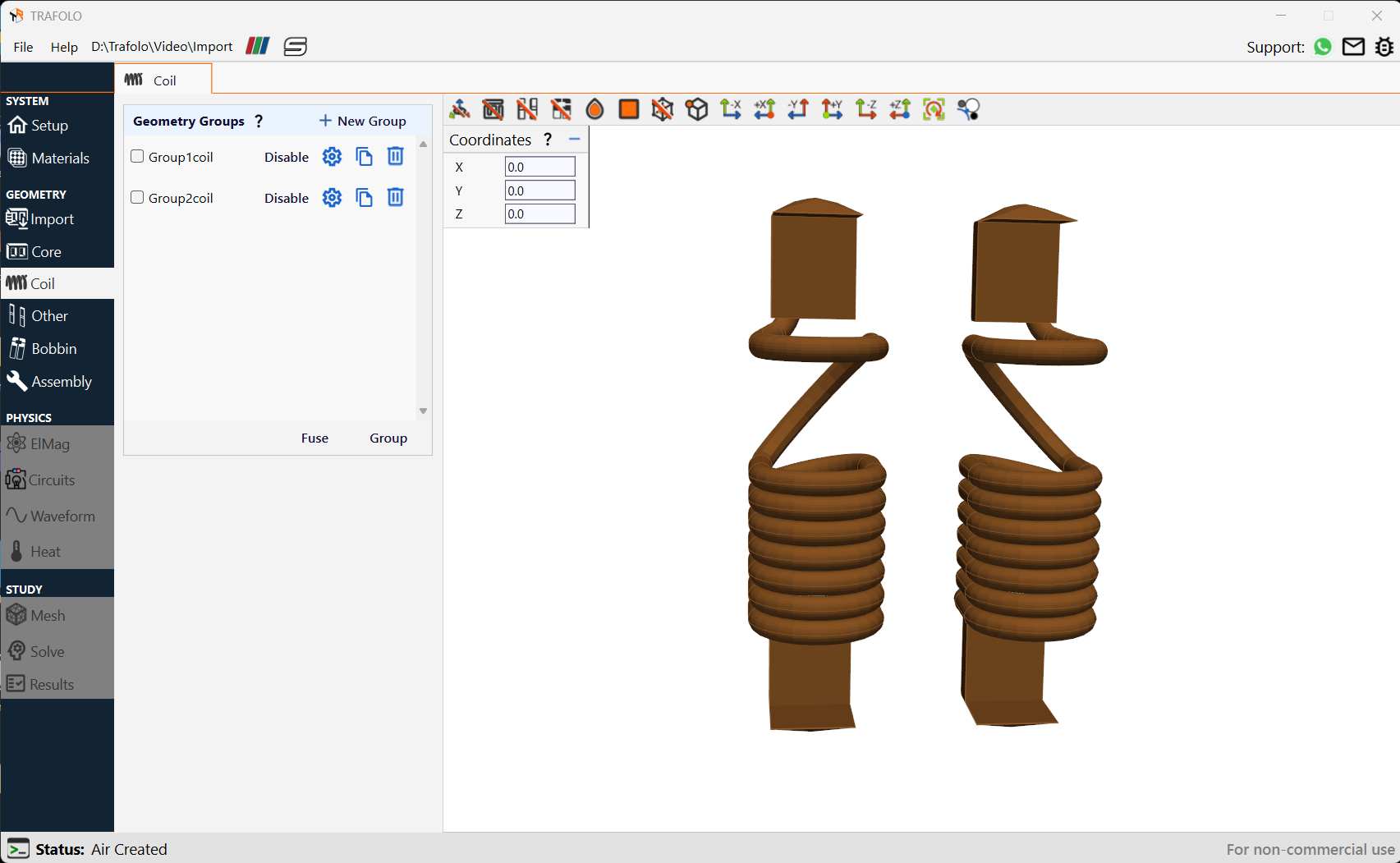
Importing through the Geometry module
Alternatively, geometries can be imported through the corresponding Geometry tab. For example, to import a coil geometry, follow these steps:
- Create a New Group in the Coil tab. A new coil group will be added to the list.
- Open the coil group Settings.
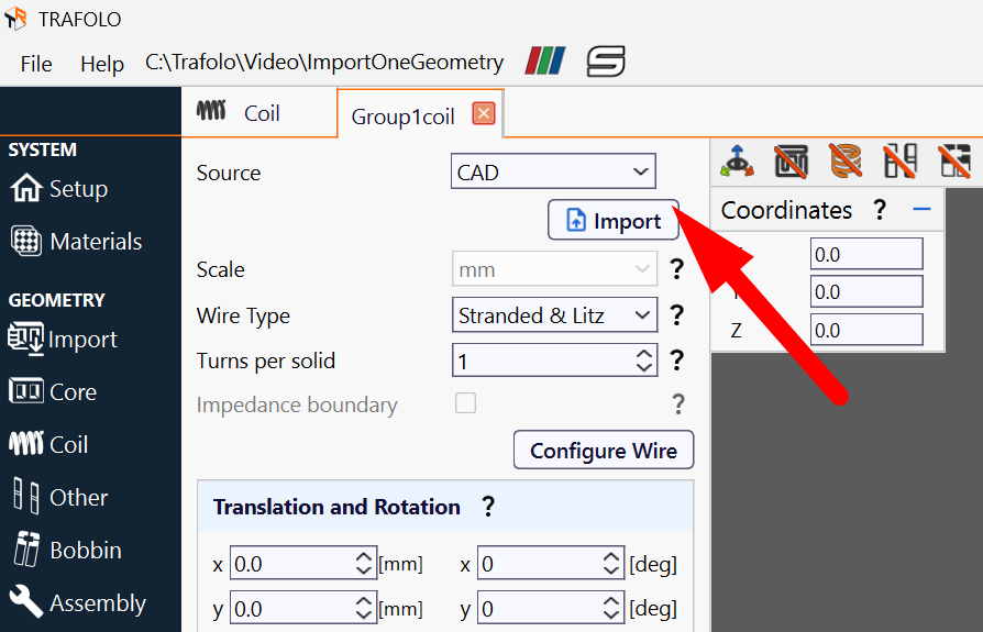
- Change Source to CAD, and click Import.
 4. Provide the file path, Scale, and other settings in the Import CAD window.
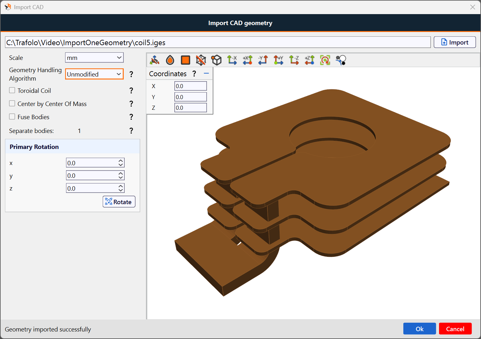 5. Click Ok to accept the imported geometry.
When importing CAD such way, a single file is expected. This file can contain any number of geometries such as multiple turns of core pieces with gaps.