Leakage Inductance (combined with Inductance (frequency and excitation sweeps))
Leakage inductance arises due to imperfect magnetic coupling between transformer windings. In an ideal scenario, all magnetic flux generated by the primary winding would be fully linked to the secondary winding. However, in reality, a portion of the flux remains unlinked, creating leakage flux and contributing to leakage inductance.
The computation process involves exciting the primary winding with its rated current while shorting the secondary winding, either by applying 0 Ω resistance or setting the secondary voltage to 0 V. This induces a current in the secondary winding that flows in the opposite direction to the primary current. The flux that does not couple between both windings is identified as leakage flux, contributing to inductance.
Leakage Inductance Simulation Setup
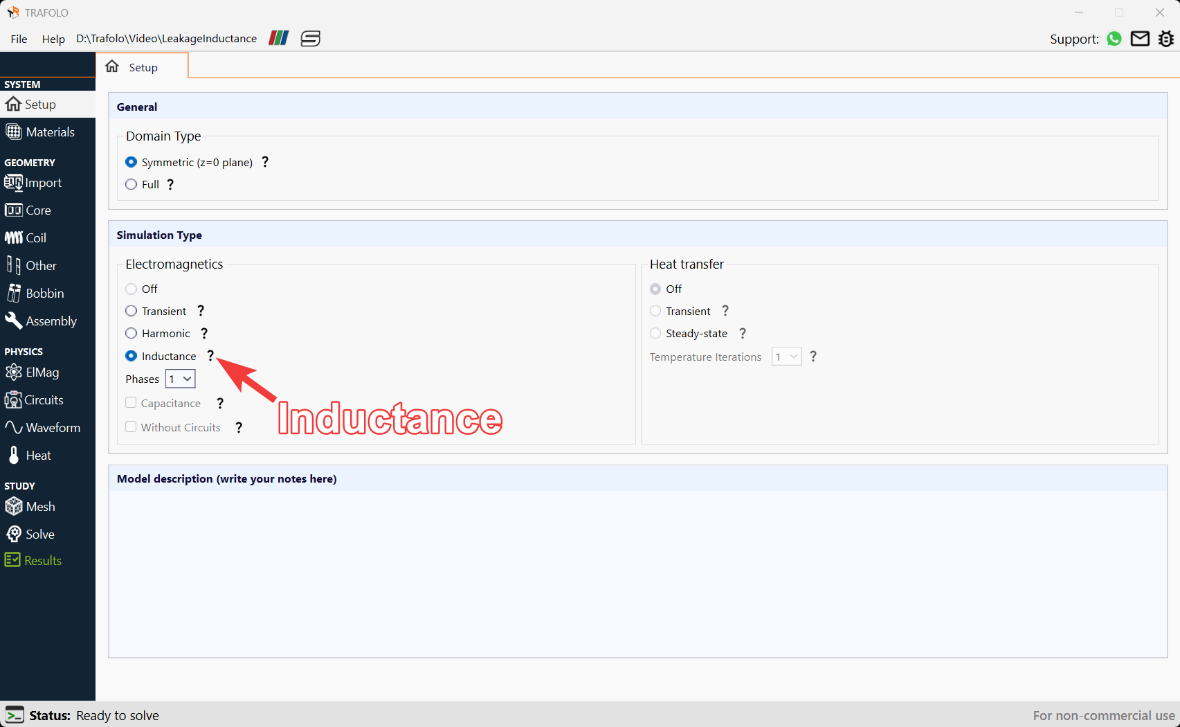
For inductance computation (including magnetizing), select the Inductance Simulation Type in the Setup tab.
The Inductance option conducts a sweep analysis based on harmonic simulations to calculate inductance, reactance, Q-factor, losses, and other related parameters across different currents, voltage levels, or frequencies.
Setting winding excitations
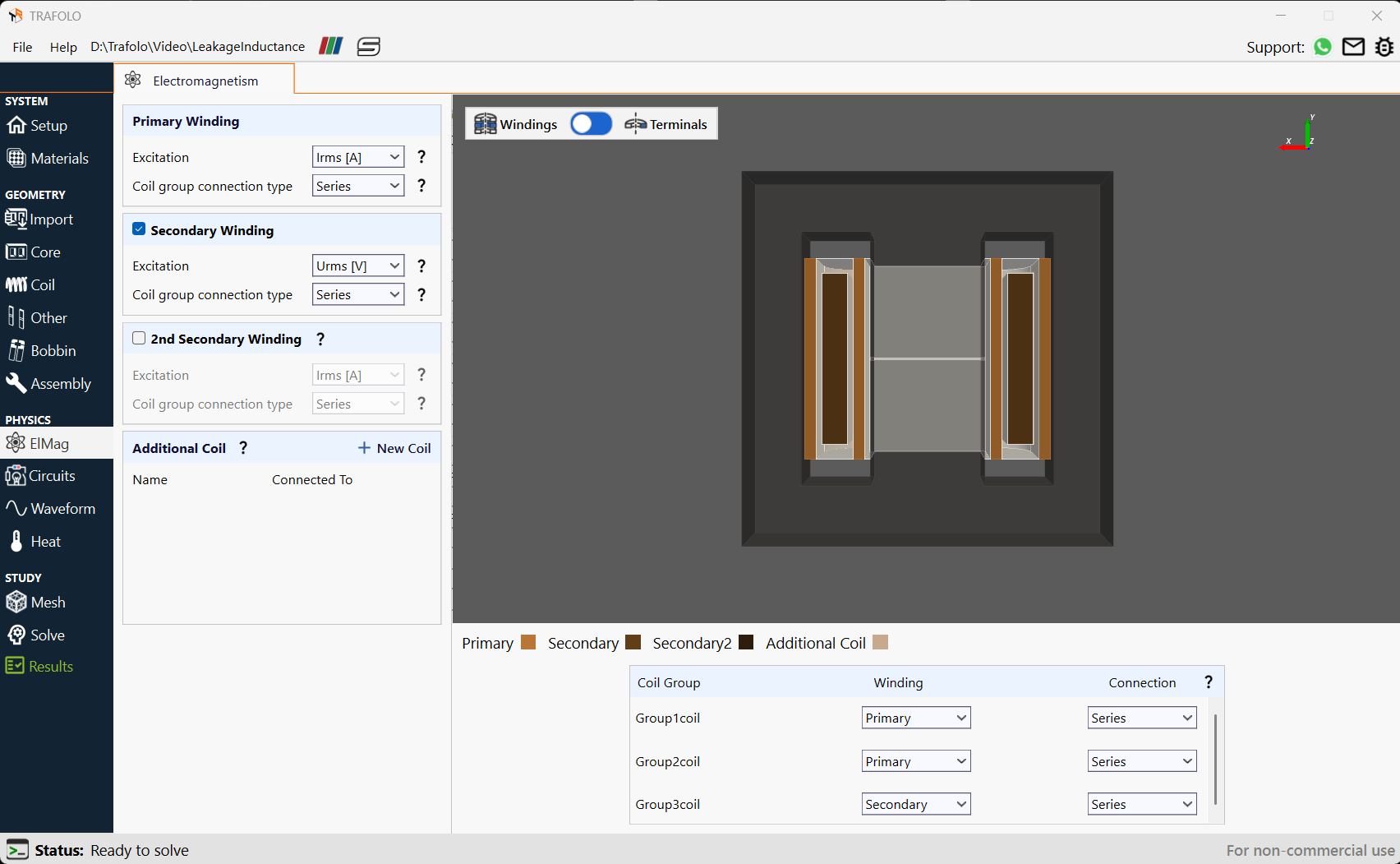
The key difference between leakage inductance and magnetizing inductance lies in the behavior of the secondary winding. For reference, no current flows in the secondary when calculating Magnetizing Inductance.
For measuring leakage inductance, the secondary winding should be shorted, allowing an induced current to flow. This current interacts with the primary and produces a magnetic flux, and the portion of flux that does not couple between the windings contributes to leakage inductance.
Excitation setup
The users can perform two types of sweep in TRAFOLO:
- Excitation as voltage or current
- Frequency
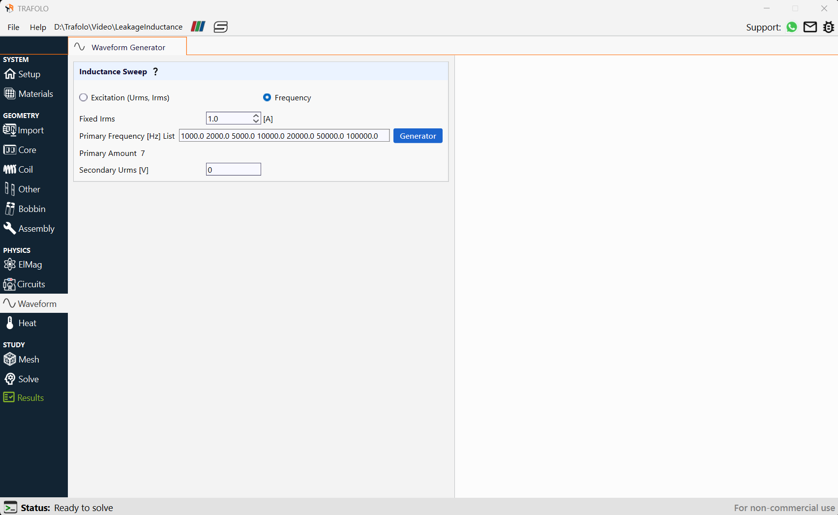
In the figure given below a frequency sweep is performed to find leakage inductance for different frequencies. Values for sweep are provided as a list of numbers separated by space.
Also, the Secondary Urms[V] is setto0since voltage excitation is given in the secondary winding. Setting the voltage across the secondary winding to 0 is equivalent to shorting the secondary winding or setting no resistance on terminals. This configuration gives the leakage inductance.
Analyzing Leakage Inductance
Calculating Leakage Inductance
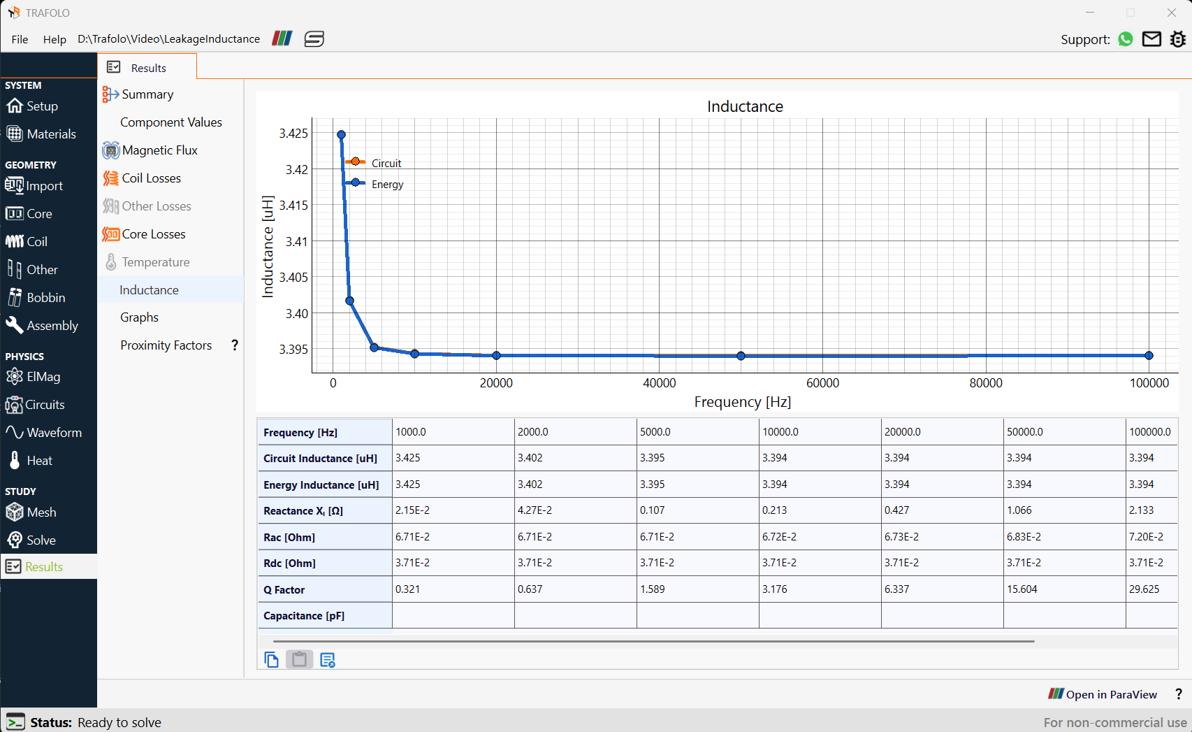
Leakage inductance is calculated using two methods.The energy method calculates inductance by integrating the magnetic energy density over the volume and dividing by the square of the primary current. The circuits method involves dividing the complex voltage by complex current to extract impedance from it. It is observed that the Leakage Inductance decreases slightly at low frequencies, but remains constant as we go to higher frequencies.
Leakage Flux Analysis in the ParaView software
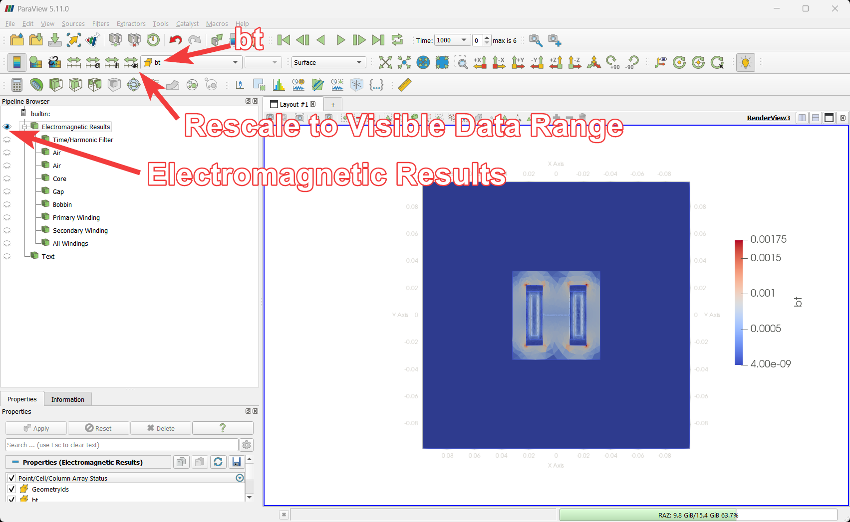
Further results can be analyzed by selecting the Open in ParaView buttonpresent in the Results tab. To examine the magnetic flux density from which leakage inductance was calculated, enable the Electromagnetic Results filter and select the bt field in the ParaView tab. Use Rescale to Visible Data Range in the ParaView tab to assess the magnetic flux density values corresponding to leakage inductance.
In the example given below, the mutual magnetic flux is primarily confined within the core, as it provides a low-reluctance path for flux linkage between the windings. However, leakage flux, which does not couple both windings, follows higher-reluctance paths through the air and insulation between the windings. As a result, magnetic field strength is higher in the leakage region compared to the core, but the total flux remains concentrated in the core.