Homogenization of Litz & Stranded Windings
Homogenization is a numerical modeling technique that captures skin and proximity effects in Litz wires without explicitly resolving individual strands. This approach is especially useful in regions with non-uniform magnetic flux, such as fringe flux near core gaps.
Directly resolving skin and proximity effects at the strand level requires an extremely fine mesh, making simulations computationally demanding. Homogenization simplifies this process by representing the collective electromagnetic behavior of the strands, significantly reducing computational complexity while maintaining accuracy.
Homogenized Simulation Setup
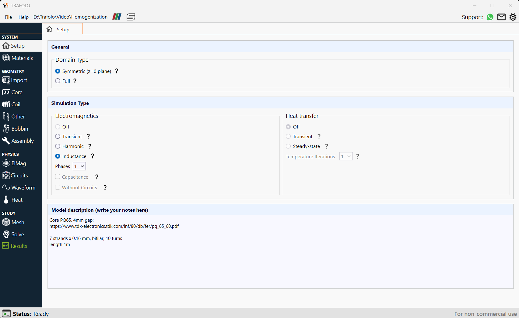
The homogenization model currently works only with the Harmonic or Inductance simulation type, which should be selected in the Setup tab.
Winding Arrangement
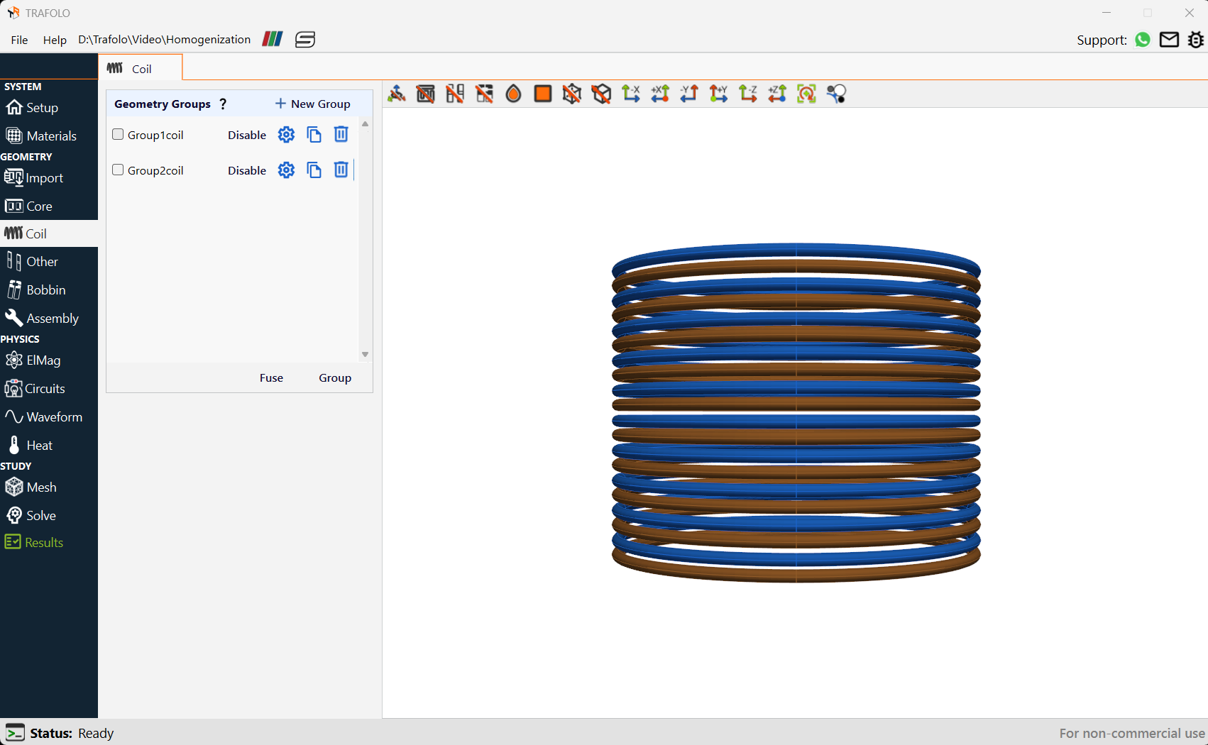
The homogenization model can be applied to any number of Litz & Stranded windings. It accounts for strand thickness, strand count, and wire position within the model. In the example below, two windings (corresponding to the Homogenization template) are connected in parallel, representing a bifilar Litz wire configuration.
For Litz wire configurations, there are two possible modeling approaches:
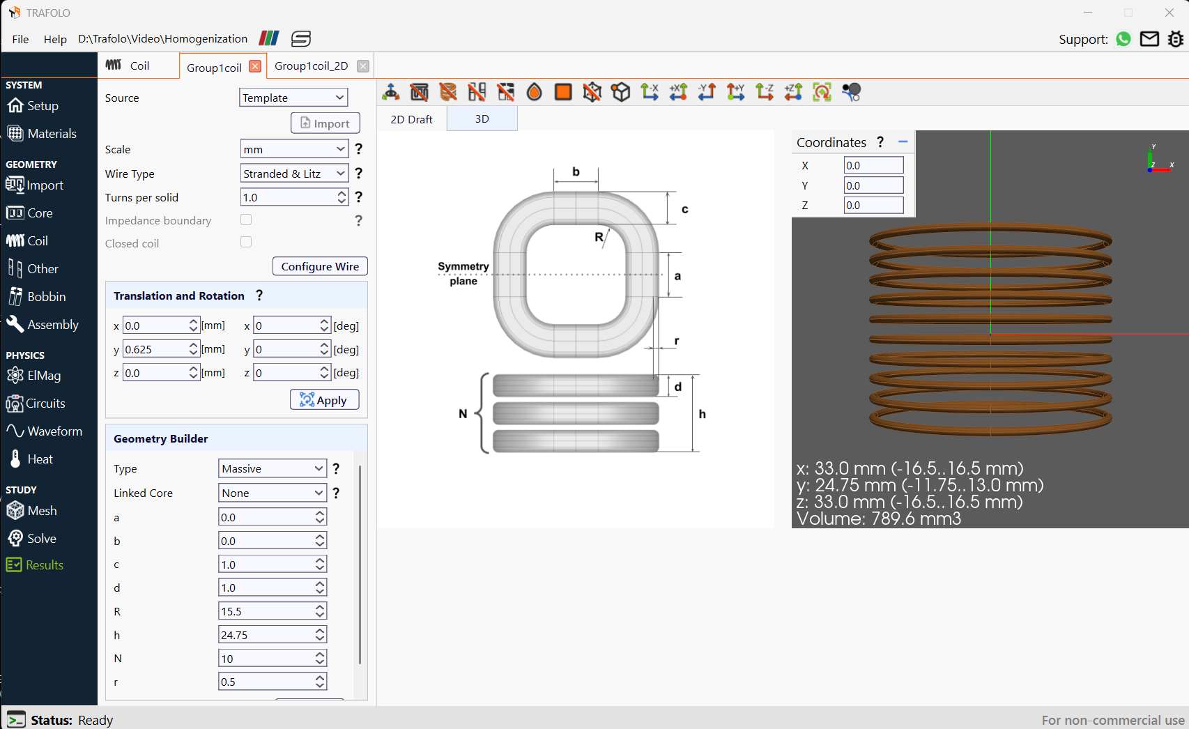
- Many-turn winding: If the winding has a large number of Litz turns, it can be represented by a simplified geometry, similar to the stranded-wire case. Here, the "Turns per solid" setting will be greater than one.
- Few-turn winding: If the winding has only a few turns, each turn can be represented individually. In this case, each separate geometry represents a single turn, as shown in the illustration below.
Litz Wire Configuration
In the Configure Wire section, Homogenization must be selected, wire settings defined, and the mesh generated. This mesh includes a unit cell representing the wire's 2D periodic structure. The simulation then evaluates the wire's response to internal and external magnetic fields, calculating homogenization parameters that are applied to the 3D model.
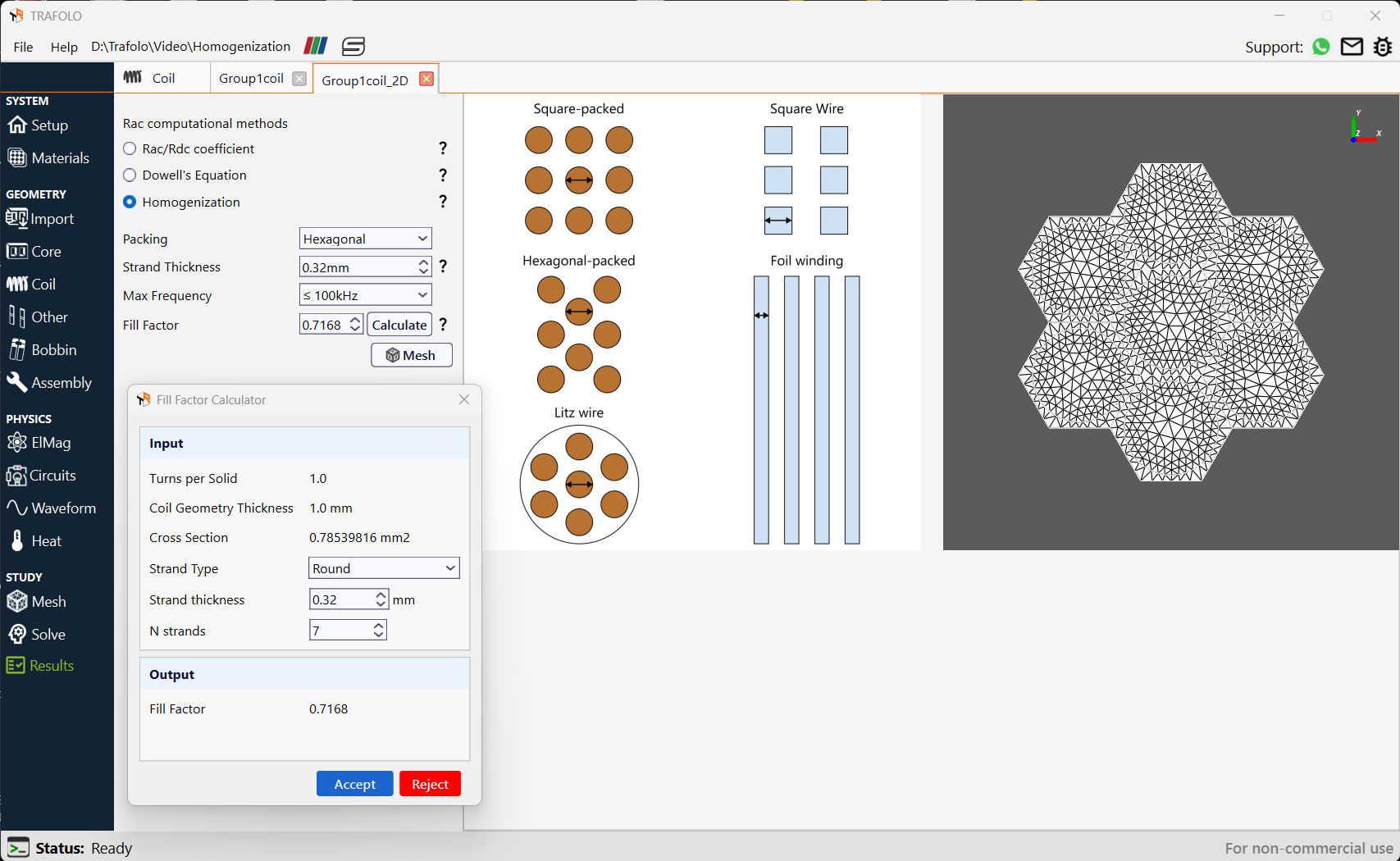
The homogenization model setup in TRAFOLO requires the user to specify the Packing type, Strand Thickness, Maximum Frequency, and Fill Factor.
TRAFOLO has a built in calculator to determine the Fill Factor. Click on the Calculate button next to the Fill factor input field, “Fill Factor Calculator” will show up. Here, describe the Strand Type and N strands.
Turns per Solid and Coil Geometry Thickness are defined at an earlier stage and the cross-section is automatically calculated.
The image below shows the a unit cell of meshed geometry of a Stranded or Litz bundle using hexagonal packing. The mesh outlines individual strands and the insulating gaps between them. This 2D simulation is used to precompute the electromagnetic response of litz or stranded wire to both internal and external magnetic fields, serving as an effective material property for the following 3D simulation.
Transient Waveforms
The homogenization model is not yet available for transient simulations, however, users can first decompose the waveform into its harmonic components, perform a harmonic simulation to compute frequency-dependent losses, and then apply effective Rac/Rdc calculated in harmonic simulation for their transient simulation. A more detailed explanation is provided in Transient Waveforms section of the User’s Guide.
Analyzing Results
Total losses, Inductance, and coil losses are analyzed in the Results tab.
Loss Summary
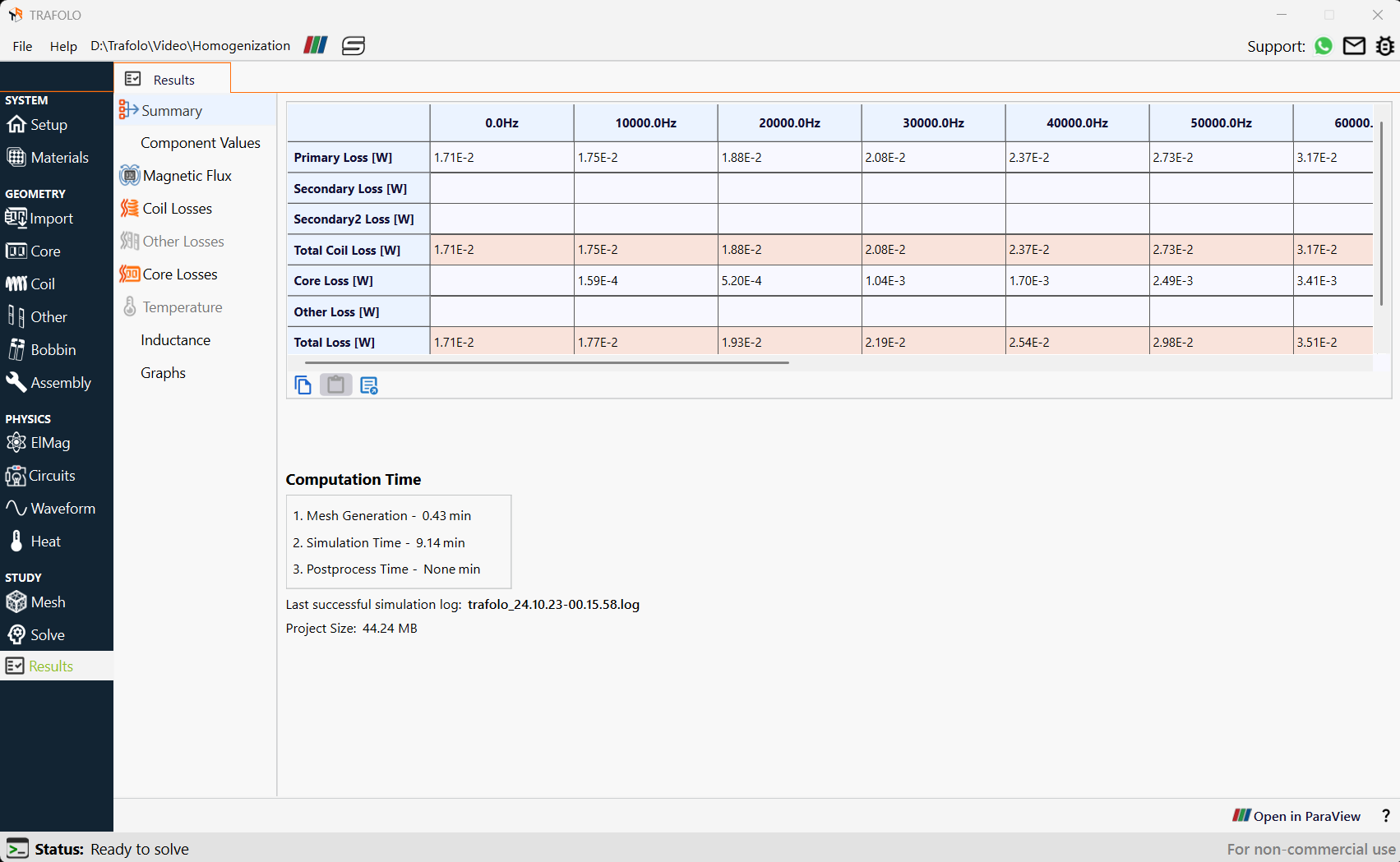
The Summary tab displays loss values for windings over a range of frequencies.
Circuit Component Values
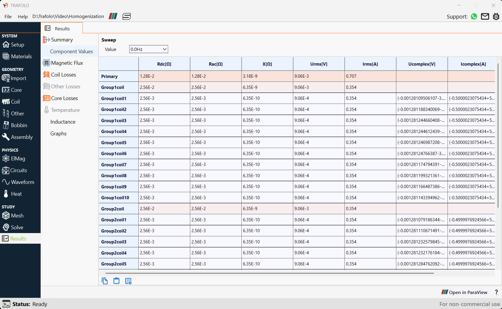
The Component Values tab provides voltages, currents, and resistances for individual winding geometries and groups.
Note that these values represent circuit-level parameters, meaning Rac corresponds to the measurable resistance rather than the actual wire resistance. The true wire resistance should be determined by dividing the total losses by the square of the current.
Coil Losses
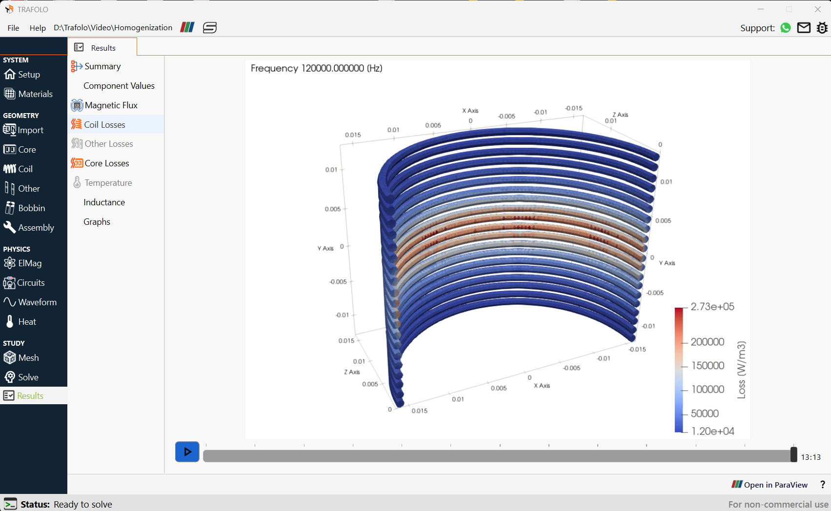
At zero frequency (DC conditions), the losses are uniform across the coil despite the air gap. This is because, at DC, there is no time-varying magnetic field, so eddy currents and proximity losses do not occur. Also, DC current flows uniformly through all litz wire strands (unlike AC conditions, where skin and proximity effects force current to concentrate in specific areas), ensuring uniform losses.
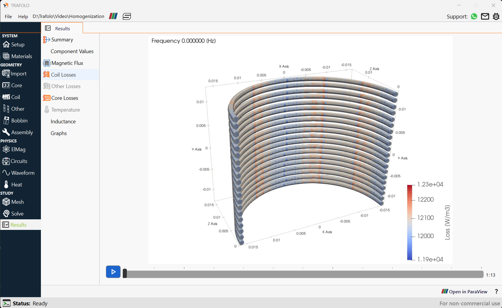
At higher frequencies, winding losses become concentrated in the center of the coil, where the air gap is located. This occurs because the air gap in the core generates fringing flux, which leads to non-uniform current distribution in conductor strands, further amplifying proximity losses.