Copy of Homogenization of Litz & Stranded
Homogenization is a numerical model that accounts for skin and proximity effects in Litz wires without resolving for individual strands, particularly in regions with non-uniform magnetic flux (such as fringe flux) near core gaps. The reason for not resolving skin and proximity effects in individual strands is because it requires a very fine mesh size which makes the simulation computationally extensive. Homogenization simplifies this process.
Setting up Simulation
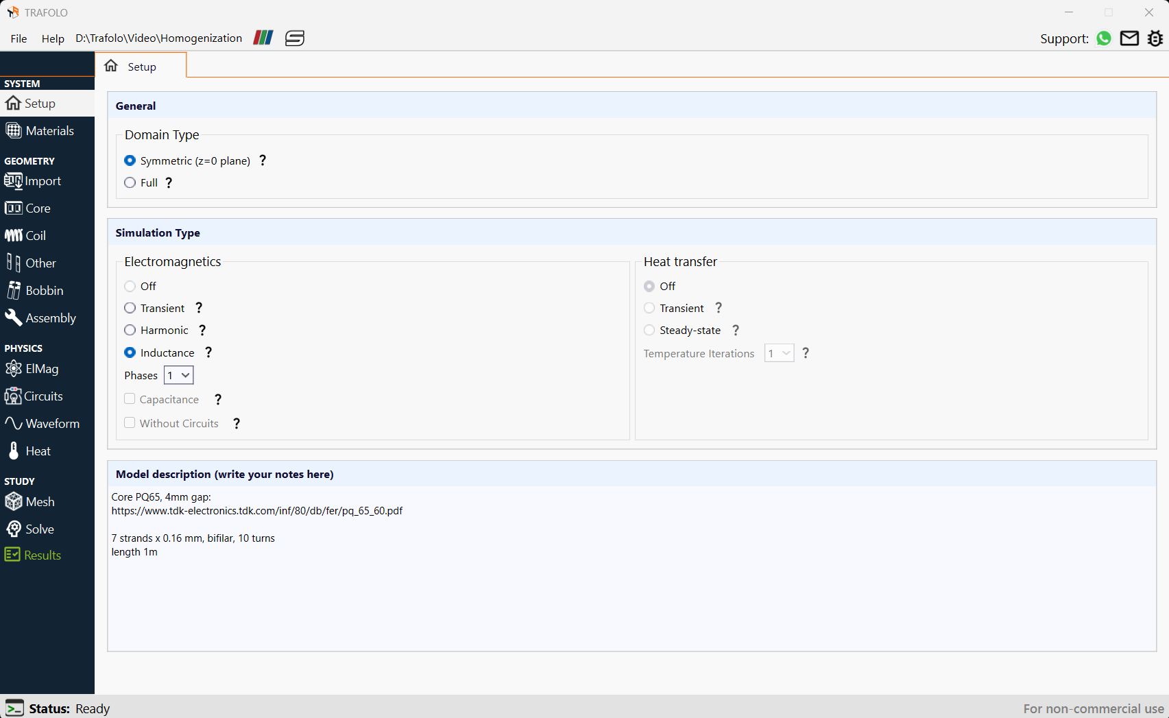
- Choose either the Harmonic or Inductance simulation type in the Setup tab for the homogenization method. Here, Inductance is selected.
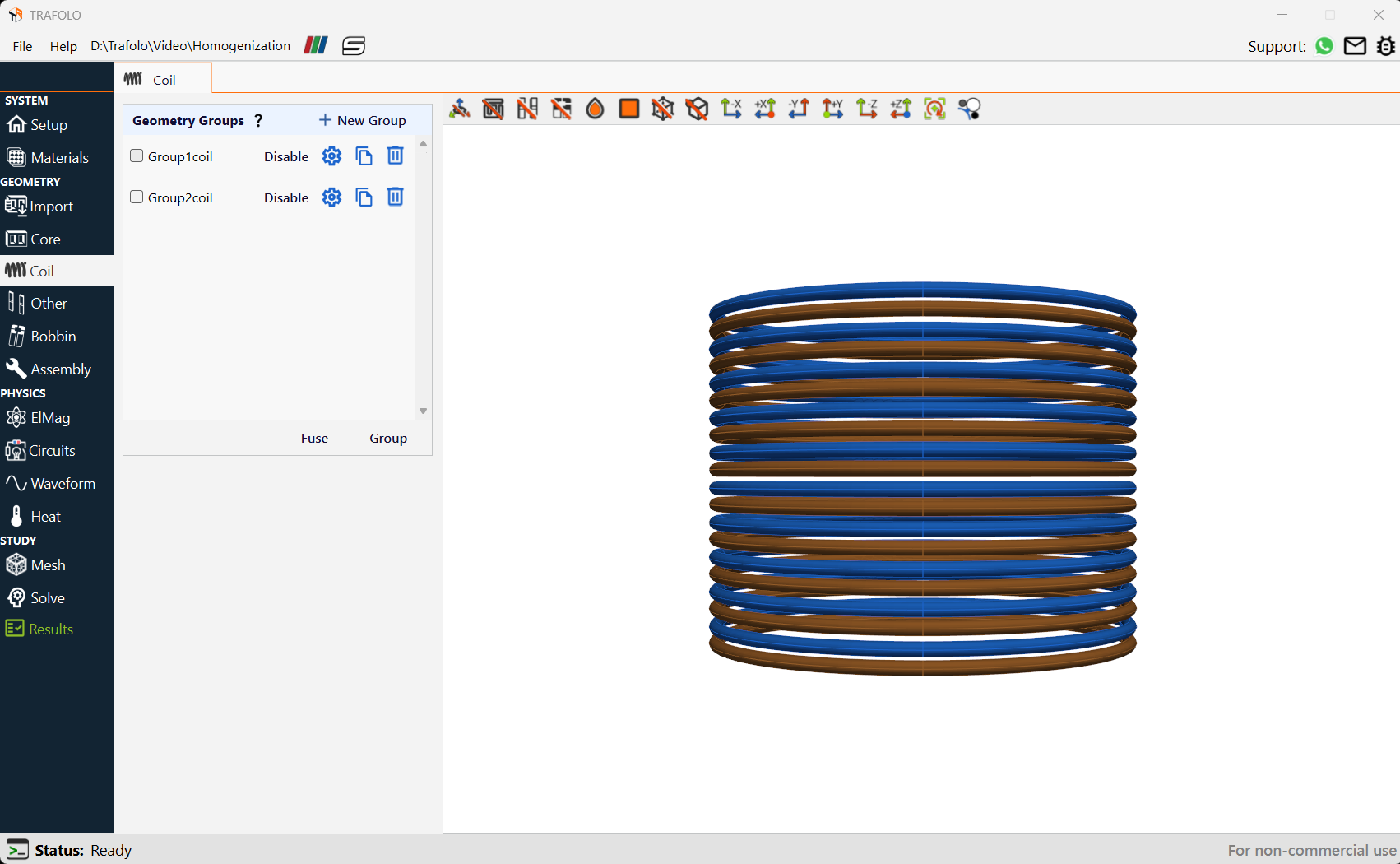
- There are two coil groups Group1coil and Group2coil respectively.
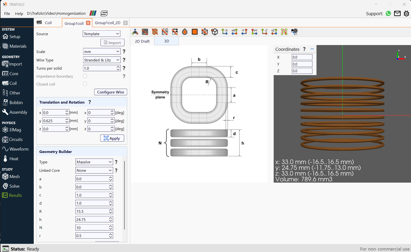
- Wire Type is set as Stranded & Litz in the coil tab. Homogenization is only available for Stranded & Litz wire type.
- Turns per solid is set as 1.
- In the Geometry Builder tab, the Type is set as Massive. Massive geometry type create coils with multiple separate geometries as one Coil Group.
- Each winding group consists of 10 turns and each turn has one wire. Each of the turns represents a separate Litz wire bundle.
Litz Wire Configuration
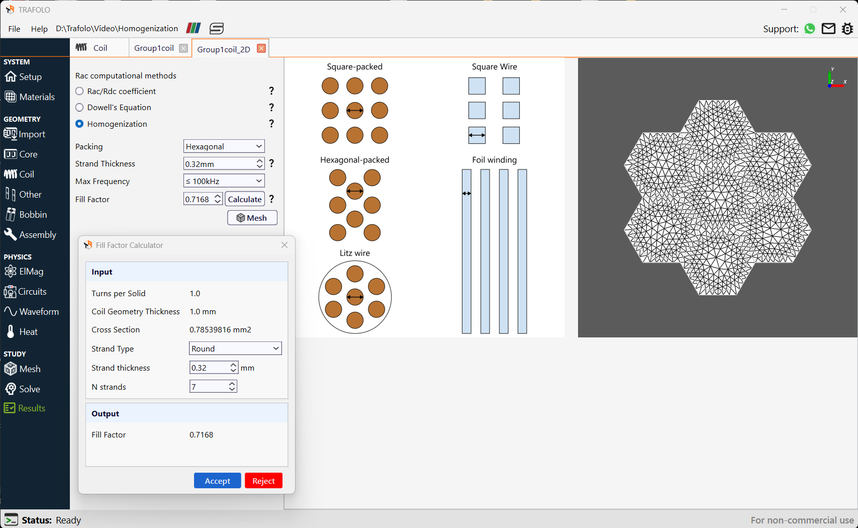
A 2D model is solved to a homogenization model to precalculate six homogenization parameters. The homogenization model setup in TRAFOLO requires the user to specify the Packing type, Strand Thickness, Maximum Frequency, and Fill Factor. The Strand Type is specified as Round and the number of strands is taken as 7 due to the presence of seven strands within the litz wire.
Analyzing Homogenized Litz & Stranded Wire
Total losses, Inductance, and coil losses are analyzed in the Results tab.
Summary
The Summary tab provides the average values of losses for homogenized Litz & Stranded wire across various frequencies.

Analyzing Winding
The Component Values tab provides voltages and currents for individual winding geometries and winding groups. Complex voltages and currents are given for individual winding geometries.
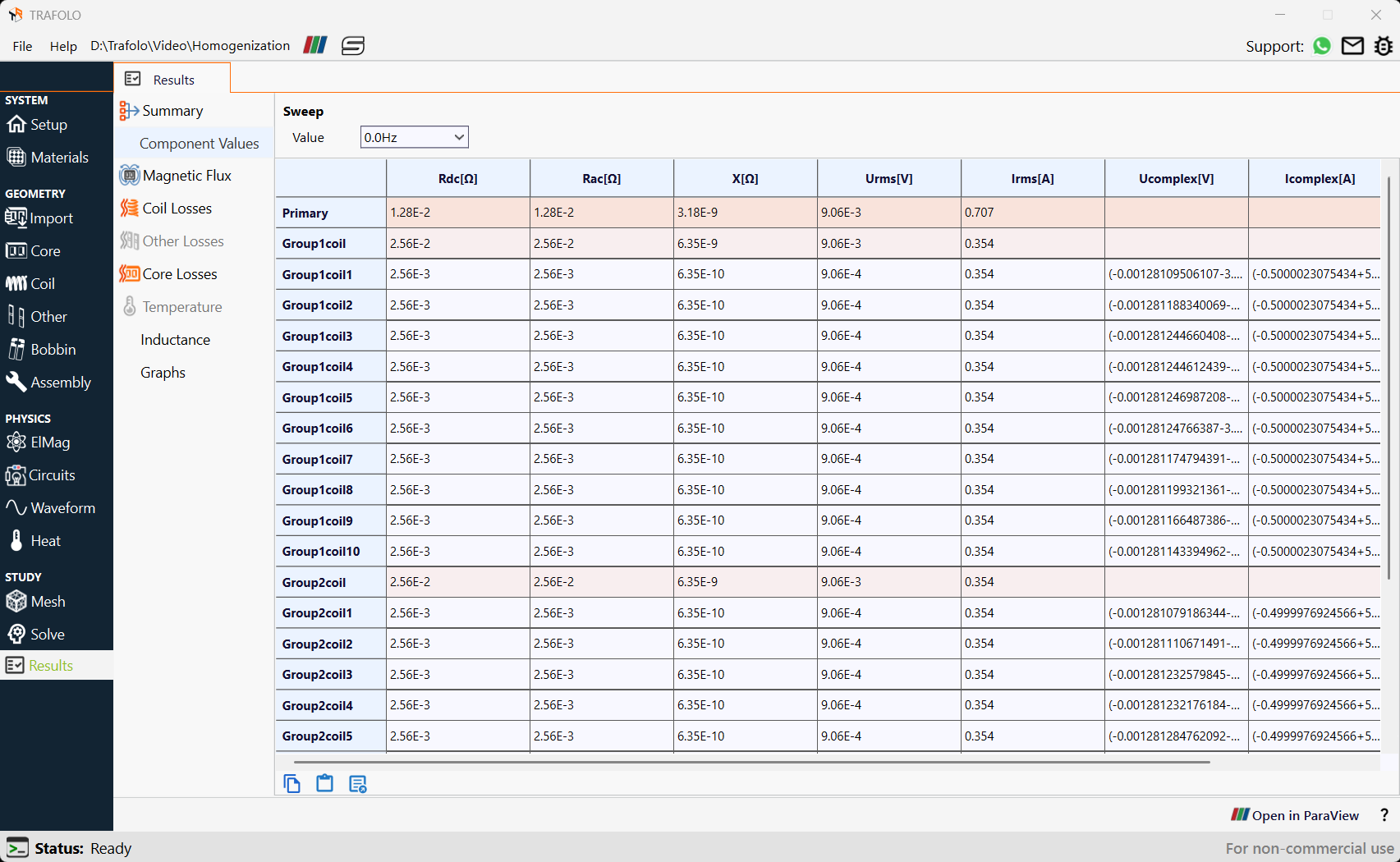
Rac and Rdc resistances are calculated at thirteen different frequencies.
Calculating Inductance
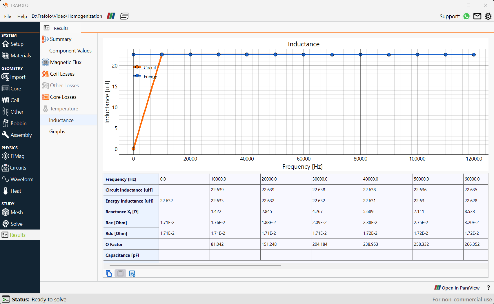
There are two methods to calculate Inductance.
- The circuits method involves dividing complex voltage by complex current to extract impedance.
- The energy method involves integrating magnetic fields and dividing by the square of the primary current.
Circuit Inductance increases from 0Hz to 1000Hz and then remains constant for the remaining frequencies with slight variations whereas Energy Inductance remains constant for different frequencies with slight variations. AC Resistance increases with increasing frequency whereas DC resistance remains constant with increasing frequency.
Coil Losses
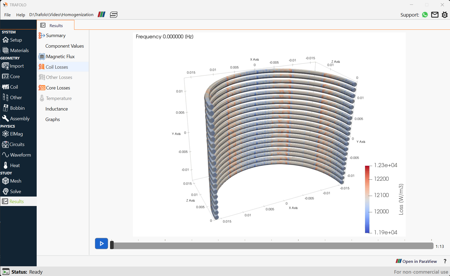
Losses are higher in the middle of the coil (where an air gap is present) than in the outer part of the coil. This is because the air gap in the core causes fringing flux which induces eddy currents in the nearby conductors, increasing their AC resistance and losses. Also, the magnetic field near the air gap is more intense, leading to non-uniform current distribution in the conductor strands, increasing proximity losses.
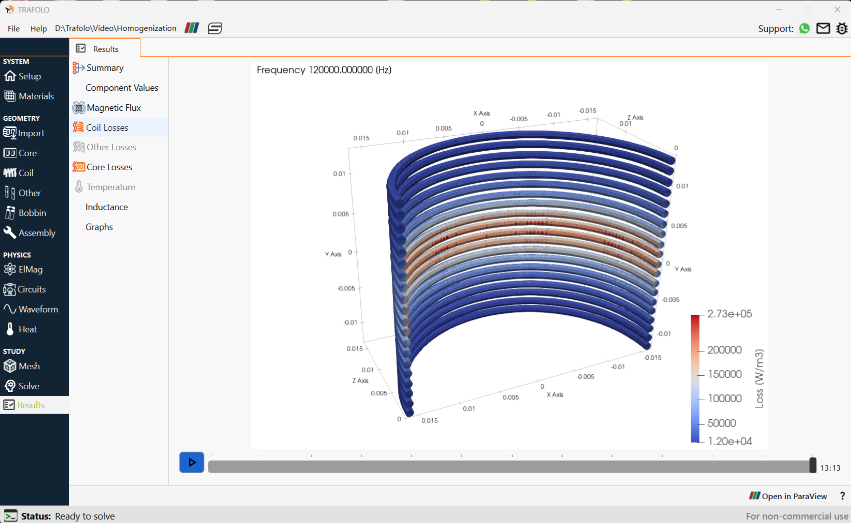
At zero frequency (DC conditions), the losses are uniform across the coil despite the air gap. This is because, at DC, there is no time-varying magnetic field so eddy currents and proximity losses do not occur. Also, DC current flows uniformly through all litz wire strands (unlike AC conditions, where skin and proximity effects force current to concentrate in specific areas), ensuring uniform losses.