Twinkle-twinkle DELTA-STAR. Lessons learned about 3-phase transformer modeling. #16
We learned 3-phase transformer modeling the hard way.
The story dates back about 1.5 years ago when our 3-phase gaped choke modeling capabilities became mainstream - capable resolving current crowding at the top/bottom surfaces and around gaps. That gave us a clear edge over equation-based models and served as a handy add-on to RALE calculations.
RALE → TRAFOLO → PROTOTYPE → PRODUCT
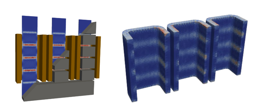
Gapped 3 phase choke model with losses in clamps and foil wingdings.
At first glance, extending to transformers looked simple: add a secondary winding, wire up the circuits, and you’re done. There are plenty of guides and papers on modeling three-phase transformers with foil and stranded windings; there’s even an ElmerFEM webinar covering the FEM side.
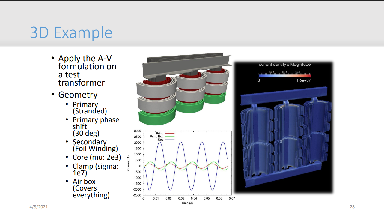
Slide from ElmerFEM webinar. https://www.nic.funet.fi/index/elmer/webinar/05-ElmerWebinar-ElmerCircuits-EelisTakala.pdf
Full video: https://youtu.be/AhKiZJa3RU8?si=Qhx10nfcEX_53Nux&t=1957
Turns out a “tasty” simulation isn’t plug-and-play: the recipes are necessary ingredients, but you still have to cook (and burn a few) before it’s right.
Avoid over-constrained circuits
So we did the normal thing - current excitation, then setting Δ–Y wiring, smash Solve button, but solver said nope. Tried every combo - windings, frequencies, even a three-air-coil minimal model - still stuck. The root cause (shout-out to the ElmerFEM circuits dev): “oh, I remember this, you have over-constrained circuits, add resistances to relax the system”.
A delta with current sources lets microscopic floating-point drift to violate Kirchhoff’s Current Law. Fix it by dropping in big resistors in parallel - physically harmless, numerically calming - so the system converges.
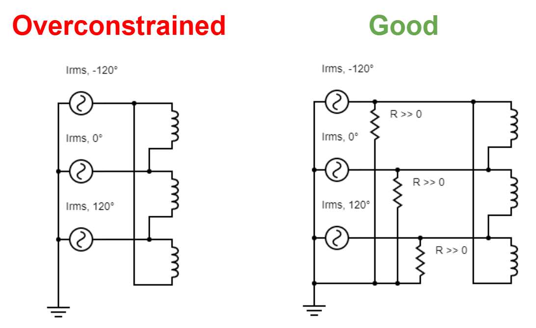
Note: Although the over-constraint issue is mainly tied to current excitation, we proactively require users to include parasitic resistors in any delta-connected circuit.
Imbalance between side limbs
Next, we hit what we thought was a bug but turned out to be a feature: an impedance asymmetry between the side limbs.
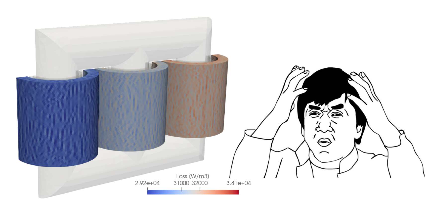
The cleanest demo to demonstrate this is a model of three voltage-driven busbars: because the side limbs have different impedances, their currents are unequal.
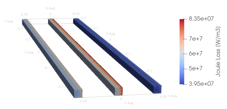
In a 3-phase core, the side limbs sit at ±120° to the center. They’re both coupled to the middle limb - one is effectively pushing while the other is pulling - so the inductance you “see” depends on how strongly they couple and where they sit in phase.
Do you have any better explanation?
Line-to-Line to Line-to-Ground
Step-down transformers are specified by line-to-line voltage. In FEM, you can’t leave potentials floating - there must be a reference node.
What to do: ground the circuit and, instead of applying line-to-line voltage, drive line-to-ground voltages. The conversion for a balanced 3-phase system V_LG = V_LL/√3.
To show where the difference comes from, take two ground-referenced sine waves - Phase 1 and Phase 2. Subtracting them yields another sine with higher amplitude and a phase shift.
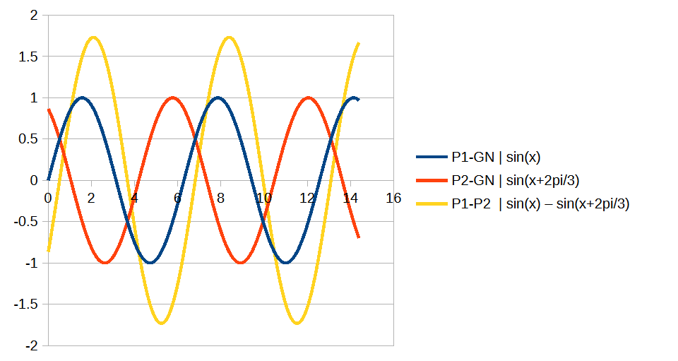
However, keep in mind that this holds only for a balanced system. In real deltas, line-to-ground voltage can drift.
Today TRAFOLO supports line-to-ground excitation only; line-to-line is on our roadmap. If that’s a blocker, tell us and we’ll bump the priority.
Removing Inrush Current in Transient Simulations
Energizing a high-power transformer by slamming all three source lines on at once isn’t ideal. As with single-phase units, inrush current is minimized when the phase voltage is applied at a moment that keeps core flux near its minimum that usually for sine excitation translates to minimum current and maximum voltage. More in our earlier article: https://www.linkedin.com/pulse/core-losses-whats-point-using-current-instead-voltage-8-trafolo-fbajf/ .
In most simulations, inrush isn’t the goal - you want the steady state. How do we skip the wasted cycles while transients settle into sines?
Harmonic simulation is certainly an option. But if you want to showcase the transient behavior to impress a client or manager, or get more likes on LinkedIn post then there are several numerical approaches; the simplest is controlled point-on-wave energization - simply speaking, switching each phase at its voltage peak.
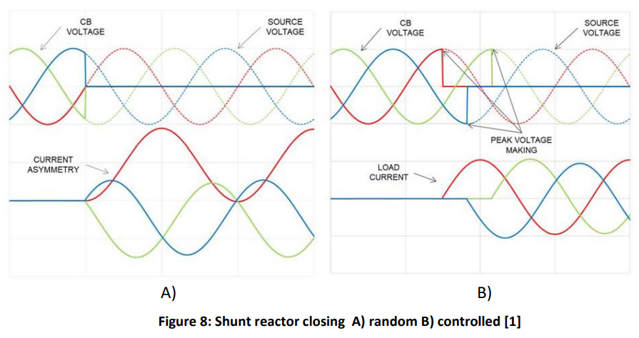
Picture from
And results are really impressive and exceeding our expectations. It takes just one period to set the tone for transformer currents.
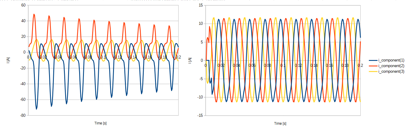
This is before
And this is after
So which one you would choose?
It’s Time for a Project
No wrap-up this time. Transient model attached. Runs ~X.0 min.
Your move - grab TRAFOLO Trial here https://trafolo.eu/download-page/. No limits other running time, hurry up, have fun!