Current Direction and Phase (V2)
In TRAFOLO, users can modify the winding direction by changing the direction of the current flow through the winding or the voltage across the winding. This feature enables us to accurately model real-world behavior, explore design variations and more.
Modifying Winding Parameters
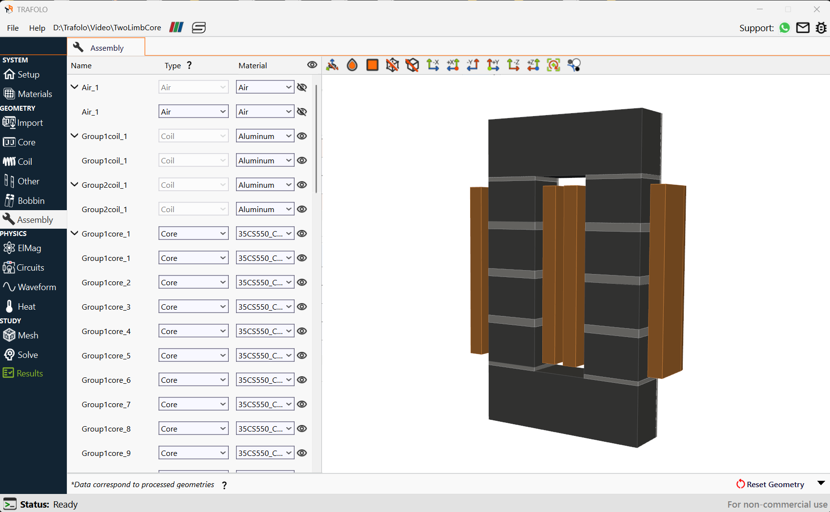
A two-limb inductor consists of a two-limb core wound by a Litz wire where distributed air gaps are given in both limbs.
Setting up Windings
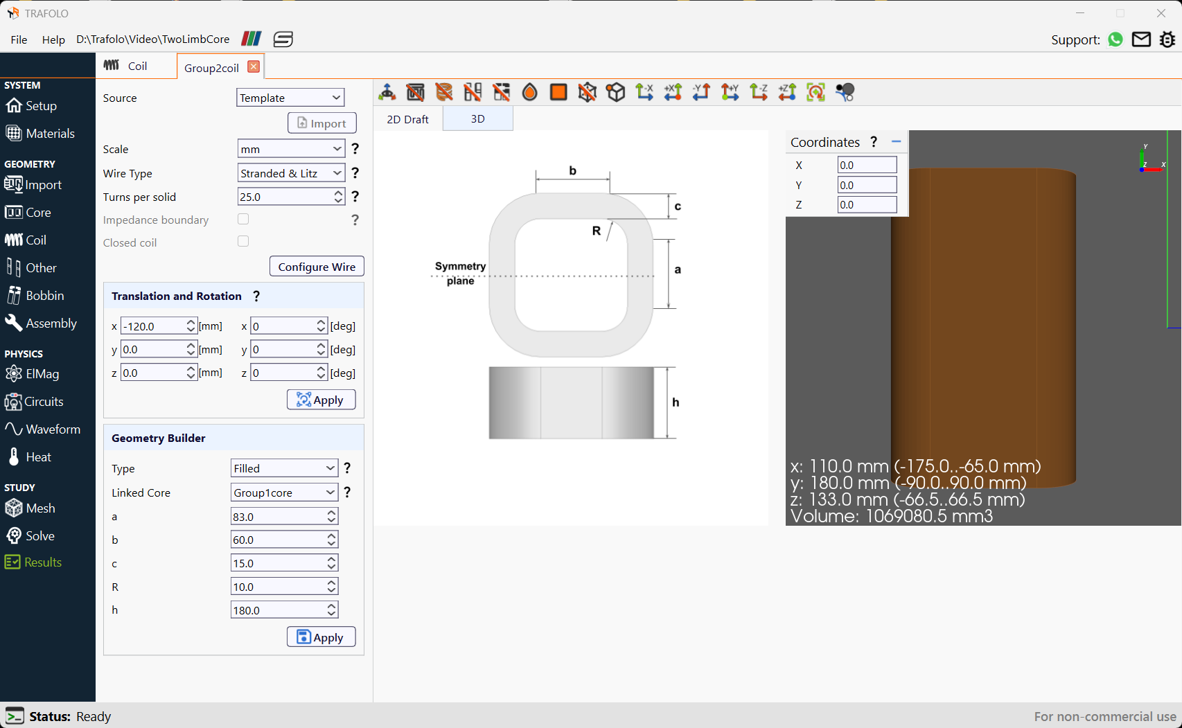
In the following example, the Wire Type and Turns per Solid are defined for the winding. Theprimary winding is copied, and a translation along the x-axis is applied to create the secondary winding. The windings are positioned on separate limbs that cross the y-axis.
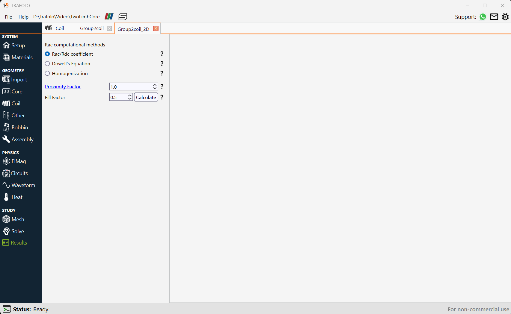
The Rac/Rdc coefficient is chosen from the Rac computational methods. This coefficient is used to adjust conductor conductivity and calculate AC resistance and losses. The Proximity Factor is only available for the Rac/Rdc coefficient method. The Fill Factor represents the ratio of conductive material to that of insulation in the winding geometry.
Configuring ElMag
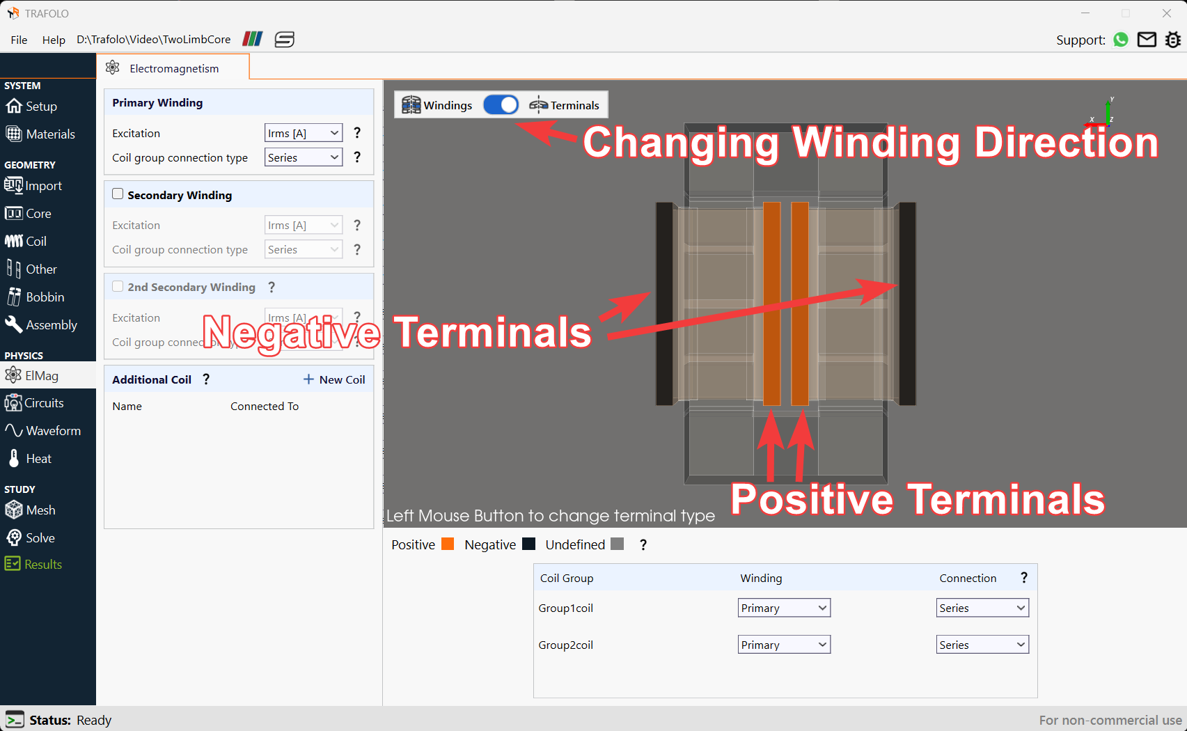
Excitation is set to Irms[A] and connect the Coil group connection type in Series to allow the same current flow through both windings. Ensure both windings are selected as Primary.
Specify positive and negative terminals to indicate the current direction. The terminal type is can be changed by clicking on the colored section of the winding, orange for positive and black for negative terminals. Currents can be set to flow in opposite directions by changing the terminal configuration.
Analyzing Results
Total losses and magnetic flux distribution are analyzed inthe Results tab.
Loss Summary
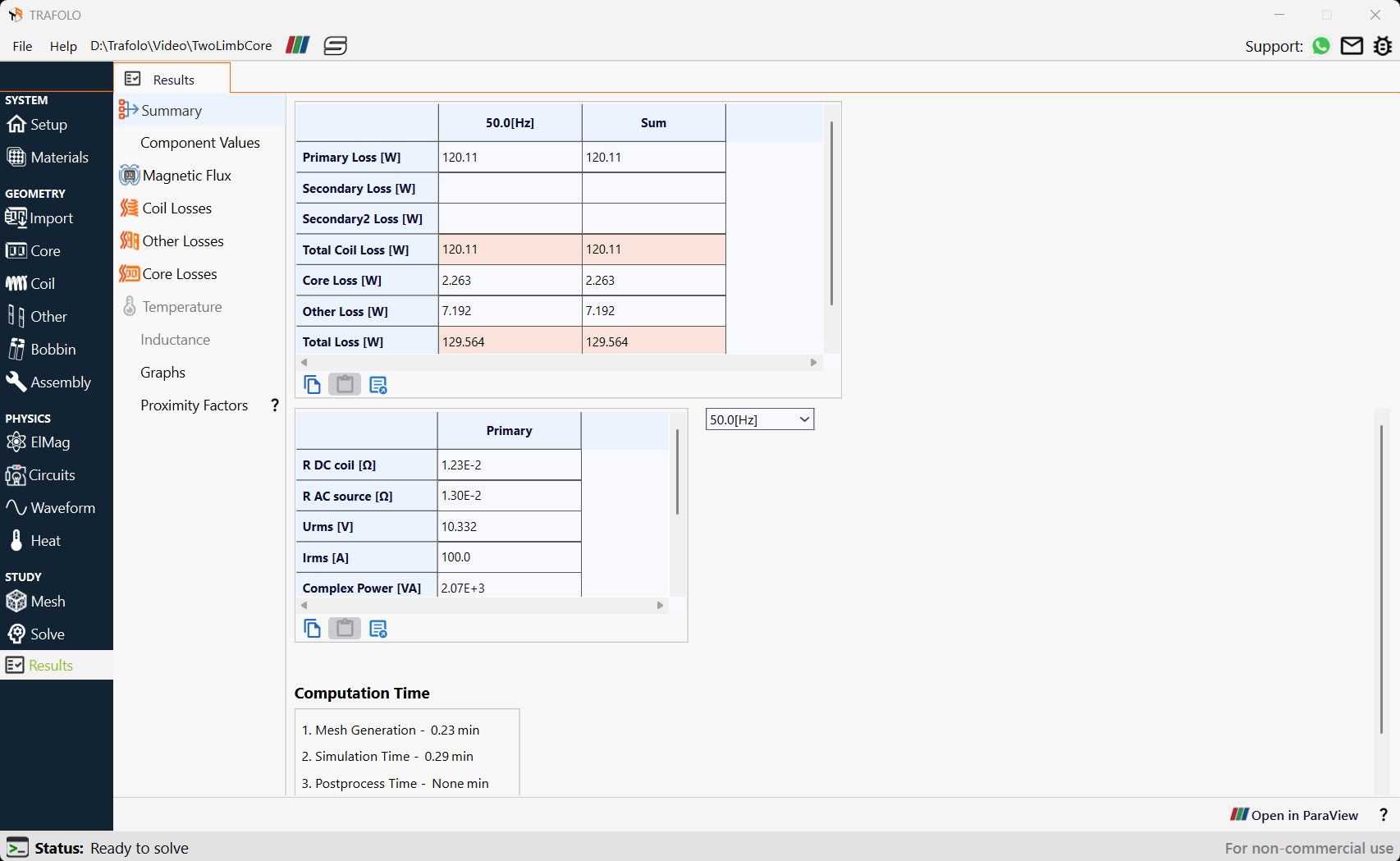
The Summary tab provides the average values of losses and electrical parameters for windings. In the figure below losses for primary winding correspond to both windings.
Winding Components
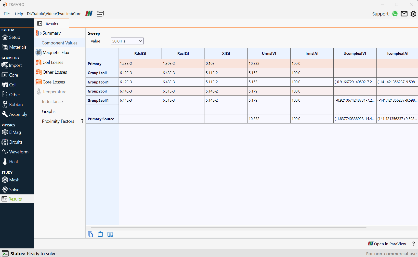
Under the Component Values tab, it provides voltages and currents for individual winding geometries and winding groups. Complex voltages and currents are given for individual winding geometries. In the figure below DC resistances, AC resistances, Reactance, RMS Voltage, and RMS current for each coil are shown.
Magnetic Flux Distribution
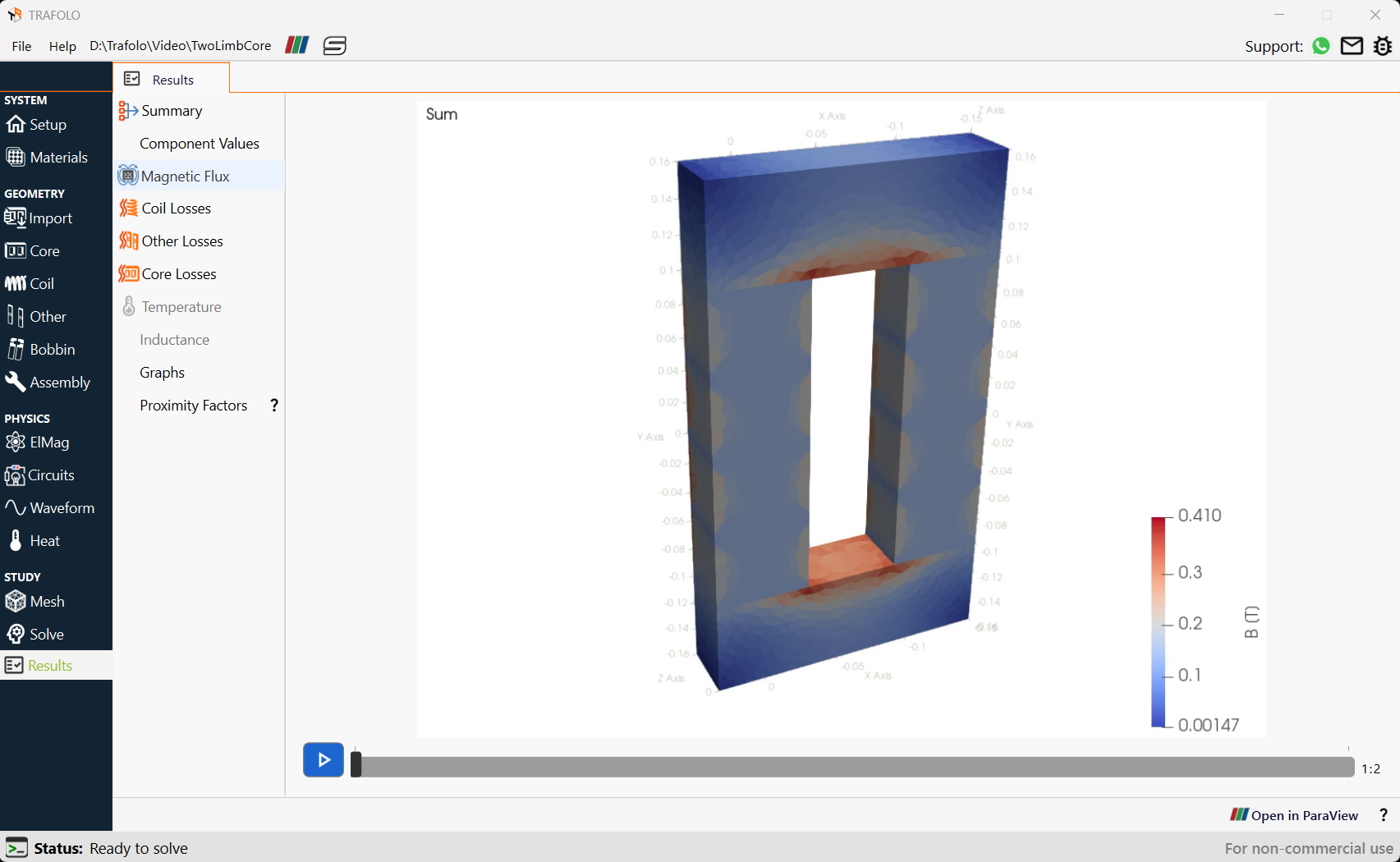
Magnetic flux is aligned in the same direction, indicating no Flux Cancellation. The current flows in clockwise and anti-clockwise direction in the two coils and a complete flux path is achieved in the core, according to Fleming’s Right Hand Thumb Rule. In the figure below both windings have currents flowing in opposite directions, ensuring correct operation.