Copy of Leakage Inductance
This user's guide demonstrates how to find Leakage Inductance in TRAFOLO. For this primary winding is excited using rated current while the secondary winding is shortedeither by applying 0 Ω resistance or setting voltage to 0 V. As a result, a current is induced in the secondary which is opposite to the primary. The net magnetic flux that remains is called leakage flux.
Setup for Leakage Inductance
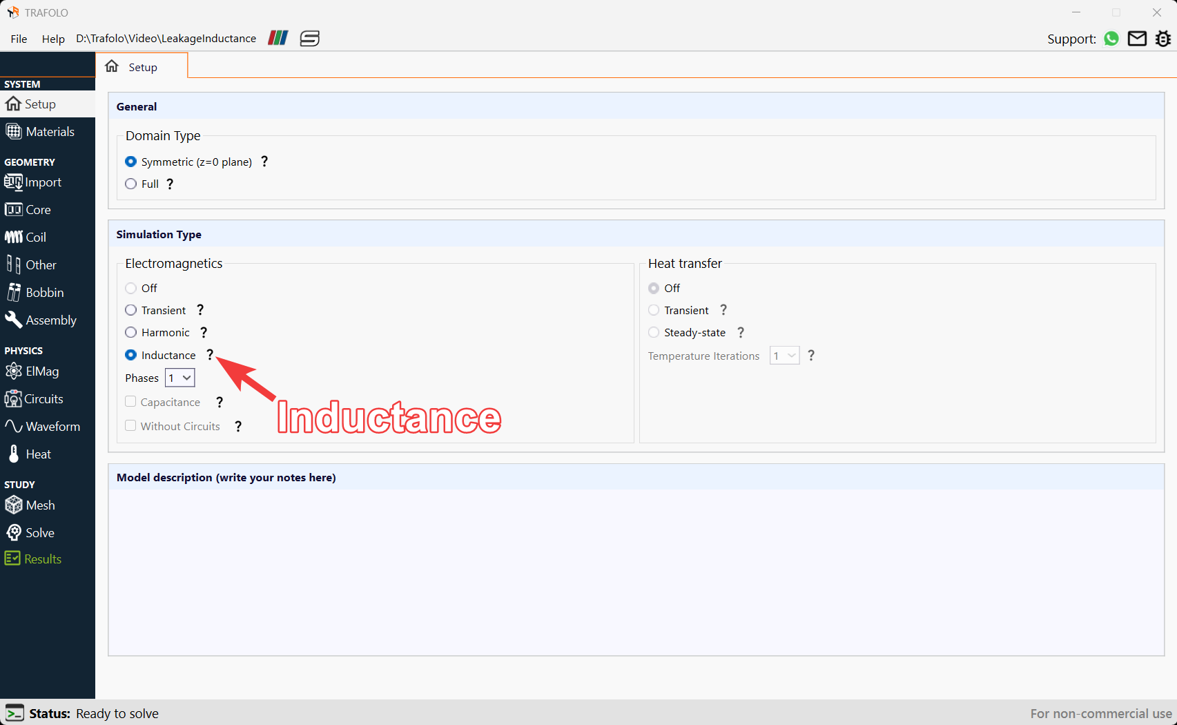
- From the model builder click on the Setup tab and choose to calculate Inductance under Electromagnetics.
The Inductance option conducts a sweep analysis based on harmonic simulations to calculate inductance, reactance, Q-factor, losses, and other related parameters across different currents, voltage levels, or frequencies.
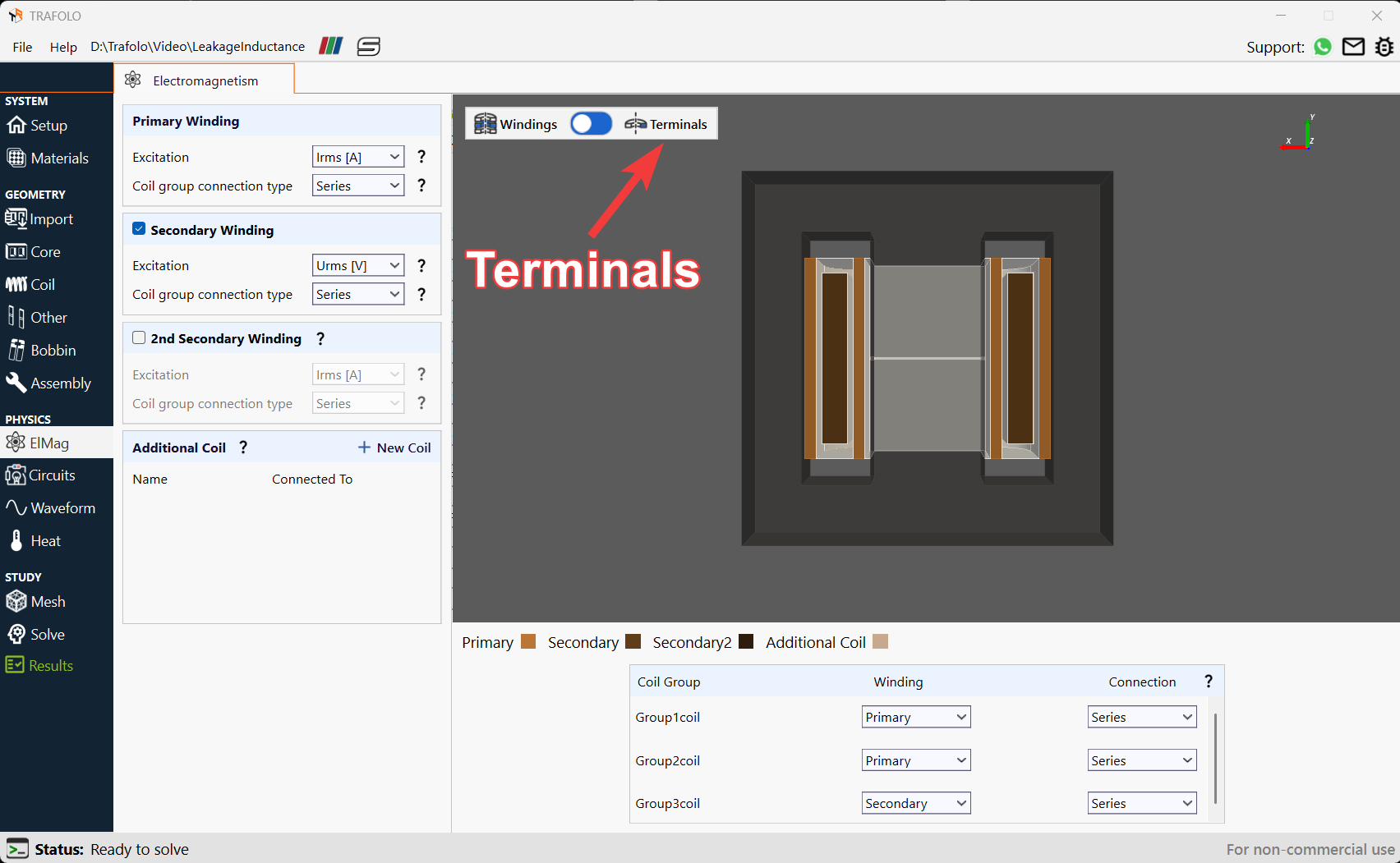
Configuring EIMag
- The Excitation in Primary Winding is set as Irms[A].
- The Coil group connection type is set as Series. Thisresults in an identical current among all coils.
- Enable the Secondary Winding.
- Choose Excitation in Secondary Winding as Urms[V] to find leakage inductance. Ensure all coil groups are connected to Primary or Secondary as needed in the EIMag tab.
- Designate Terminals as Positive and Negative.
Ensure that each turn geometry has at least one positive and one negative terminal to define the current direction.
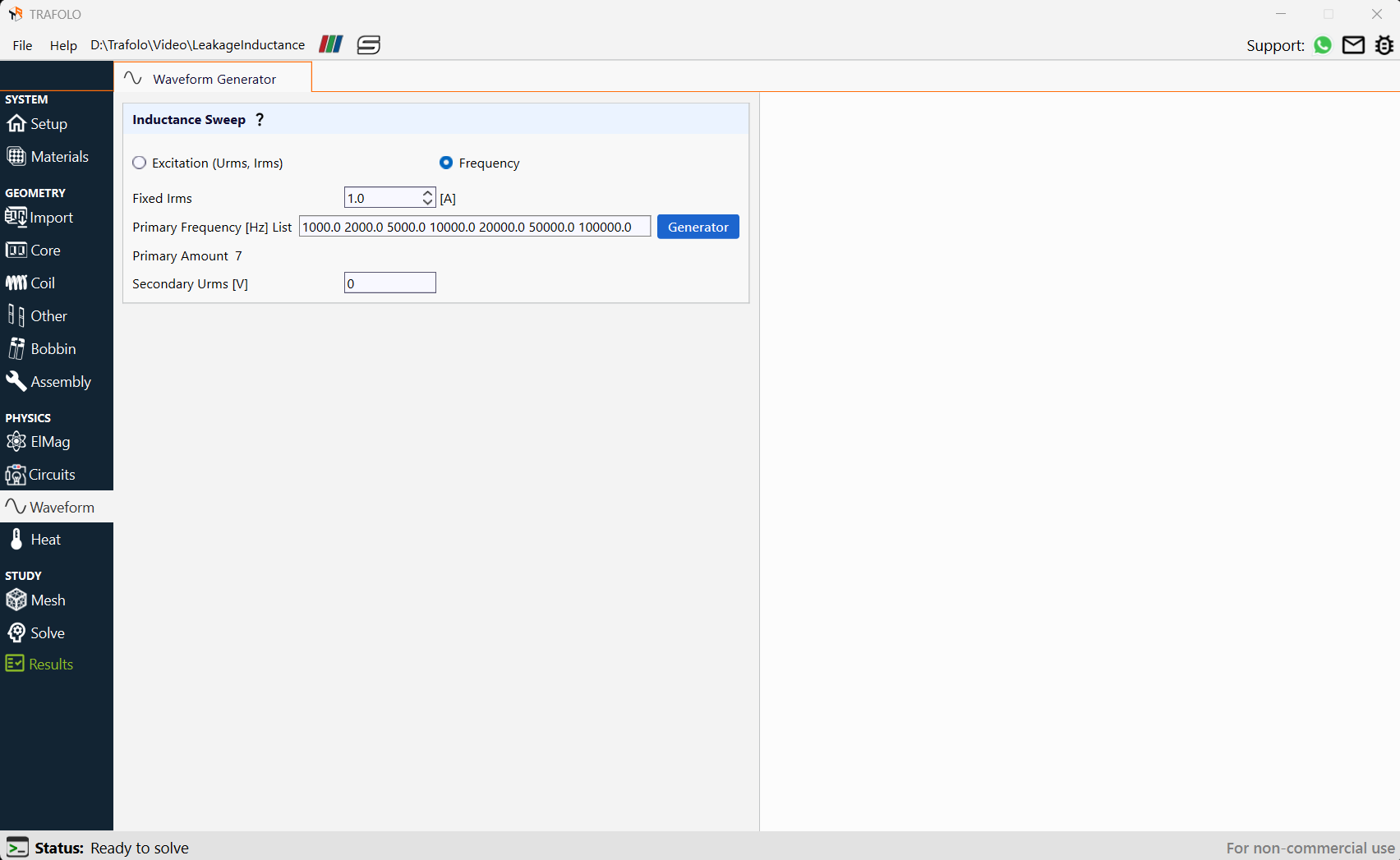
Configuring Waveforms
There are two types of sweep:
- Excitation as voltage or current
- Frequency
A frequency sweep is performed to find leakage inductance for different frequencies.
- Values for sweep are provided as a list of numbers separated by space.
- Set the Secondary Urms[V] to 0 since voltage excitation is given in the secondary winding.
Setting the voltage across the secondary winding to 0 is equivalent to shorting the secondary winding or setting no resistance on terminals. This configuration gives the leakage inductance.
Analyzing Leakage Inductance
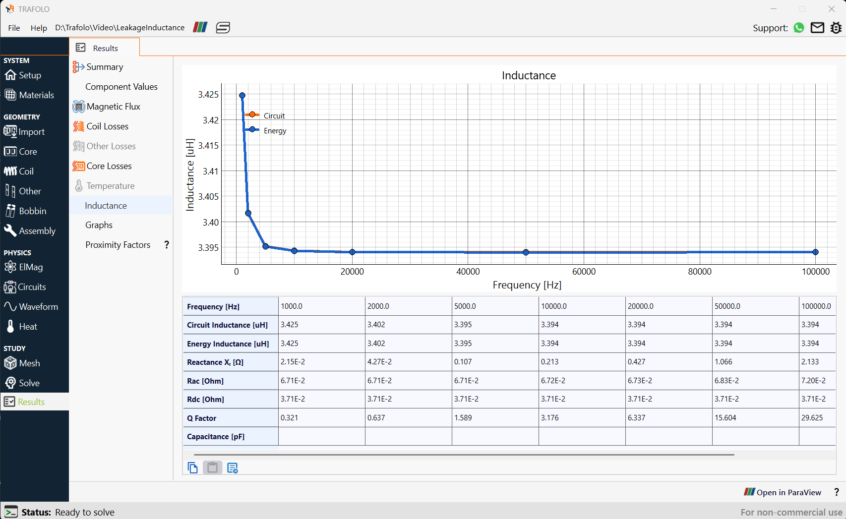
Calculating Leakage Inductance
Leakage inductance is calculated using energy and circuits. It is observed that the Leakage Inductance decreases slightly at low frequencies whereas Leakage Inductance remains constant as we go to higher frequencies.
Leakage Inductance Analysis in the ParaView software
Further results can be analyzed by clicking on the Open in ParaView buttonpresent in the Results tab.
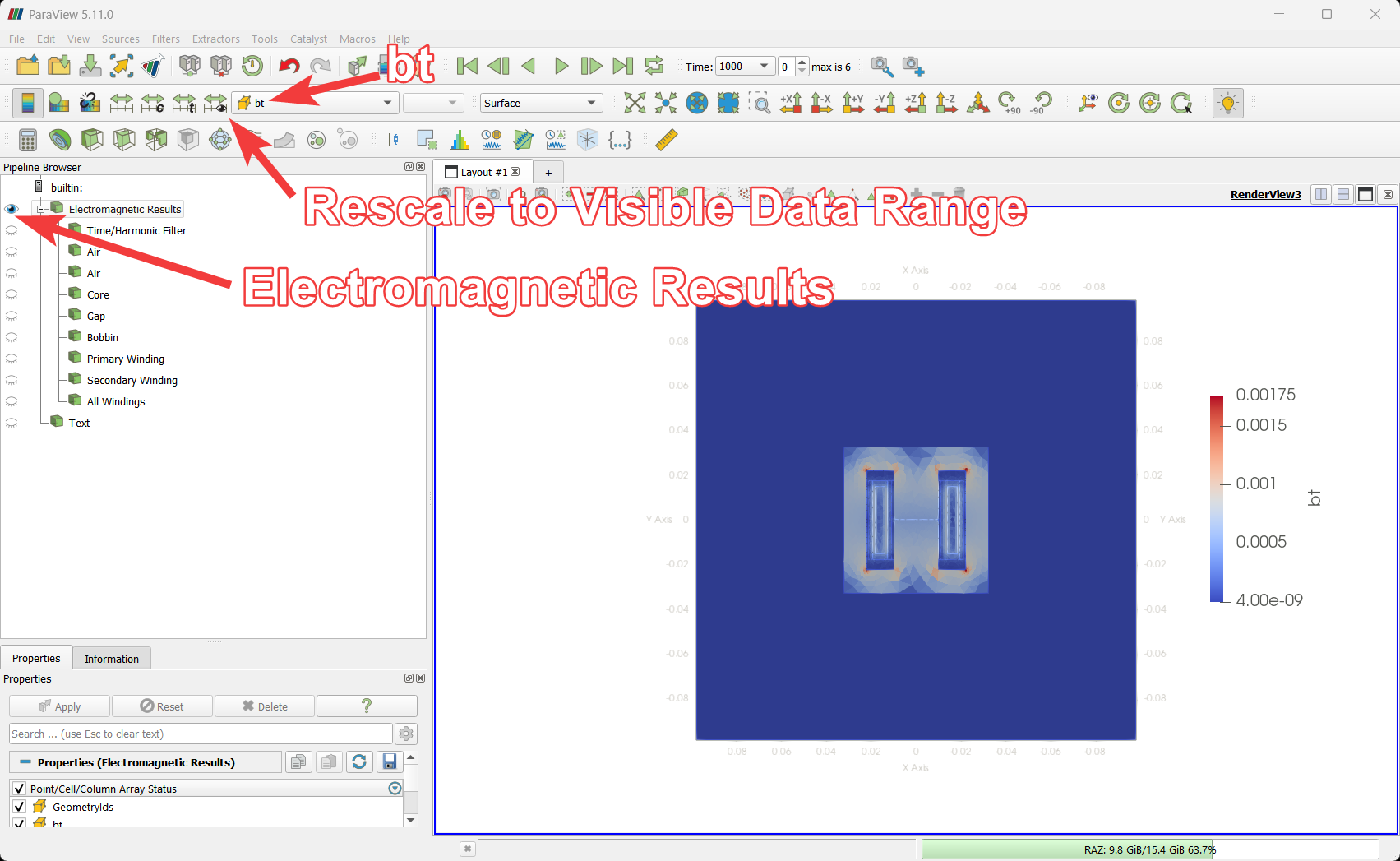
- Check the magnetic flux from which leakage inductance was calculated by enabling the filter Electromagnetic Results, and choose the field bt in the ParaView tab.
- Click on Rescale to Visible Data Range in the ParaView tab to assess the magnetic flux values corresponding to leakage inductance.
Magnetic field is concentrated more between the windings since we find Leakage Inductance.